Digital guide

You are here:

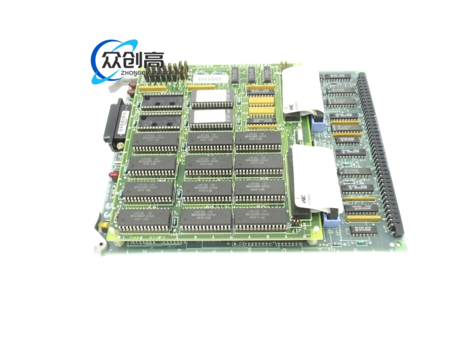
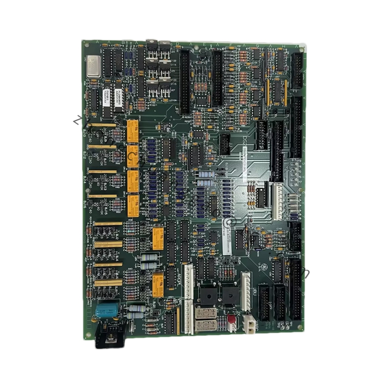
GE DS3800HFPG1E1D

  • Product Name:​ GE Mark IV Speedtronic Frequency Processor Board (HFP)
  • Introduction:​ The DS3800HFPG1E1D is a vital component in the Mark IV Speedtronic turbine control system, specifically engineered to process high-speed frequency signals from magnetic pickups (MPUs) for turbine speed control.

Detailed content

  • Technical Specifications:
    • Manufacturer: General Electric (GE)
    • Series: Mark IV Speedtronic
    • Core Function: Processes high-speed frequency signals for turbine speed control
    • Product Type: Frequency Processor Board (HFP)
    • Inputs: Magnetic Pickup (MPU) / Frequency signals
    • Revision: G1E1D (Latest engineering revision)
    • Processing: Pulse-to-digital conversion for speed loops
    • Connectors: Edge-card gold finger connectors
    • Indicators: Diagnostic Status LEDs
    • Mounting: Standard Mark IV Control Rack
    • Inventory Status: Obsolete/EOL
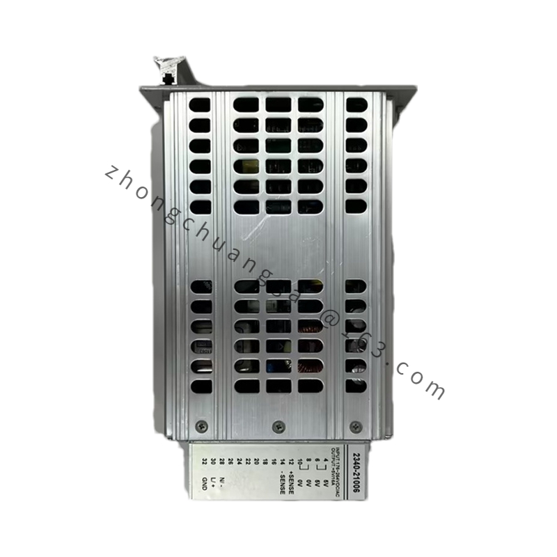
  • Features:​ Multi-channel frequency input; precision signal conditioning; Mark IV rack compatible; as a critical “insurance” spare for aging Mark IV control systems, it prevents frequency signal failure that would lead to immediate turbine trip.
  • Material & Structure:​ Edge-card gold finger connectors; diagnostic status LEDs; precision timing circuits sensitive to component drift and heat damage.
  • Working Principle:​ Converts raw MPU pulses into digital data used by the control processors to regulate turbine speed, detect overspeed conditions, and manage synchronization.
  • Application Scenarios:​ Mark IV Speedtronic turbine control systems for gas and steam turbines.
  • Installation Requirements:
    • Stage 1 (Pre-Installation): Identify the specific core where the frequency card is located; ensure the turbine is in a safe state for a control board swap; wear an ESD wrist strap to protect CMOS logic; document any hardware jumpers or manual switch settings on the existing board.
    • Stage 2 (Removal): Unlock the card retainer bars; gently extract using card pullers; avoid touching gold edge connectors; inspect backplane for dust.
    • Stage 3 (Installation): Verify jumper positions match original configuration exactly; align with rack guides and slide in firmly until edge connectors fully engaged; re-secure retainer bars.
    • Stage 4 (Power-On & Testing): Monitor diagnostic LEDs; verify speed signal accuracy on Mark IV operator interface; perform signal verification test with calibrated handheld tachometer.
  • Usage Notes:​ Purchasing as “New Surplus” rather than refurbished is essential due to precision timing circuit sensitivity; the G1E1D revision offers improved signal filtering for noisy electrical environments and is generally backward compatible.

You may also like