Digital guide

You are here:

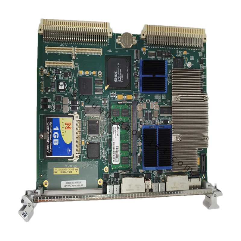
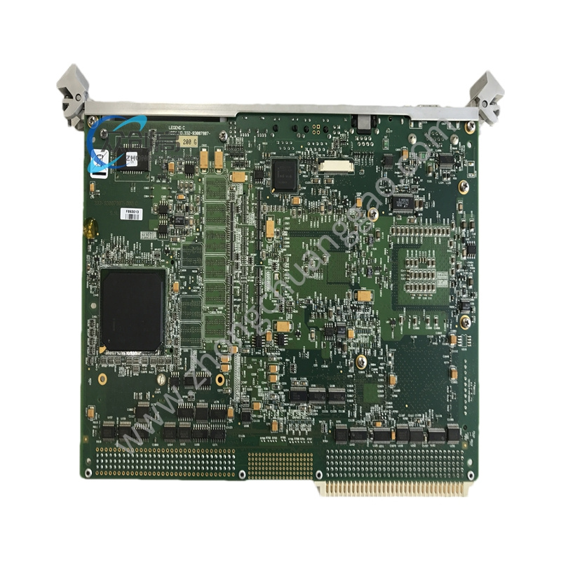
GE DS215UCIAG1AZZ05A

Product Name:​ UC2000 Core Motherboard
Overview:​ The DS215UCIAG1AZZ05A is a UC2000 Core Motherboard from GE’s Mark V Series, supporting Speedtronic turbine control systems. It integrates a microprocessor, PROM modules, and modular connectors, ensuring reliable performance in complex turbine automation environments.

Detailed content

Technical Specifications:
  • Manufacturer: General Electric
  • Series: Mark V
  • Module Type: UC2000 Core Motherboard
  • Microprocessor: 1 microprocessor
  • PROM Modules: Multiple PROM modules
  • Analog Output Channels: Up to 12 channels
  • Output Current Range: 0-20 mA
  • Common Mode Voltage: 5 V DC max
  • Maximum Lead Resistance: 15 Ω
  • Operating Temperature: -30 to +55 °C
  • Indicators: 10 LEDs for health and error codes
  • Connectors: Modular interface for daughter card
  • Dimensions: 28 × 21.42 × 2.5 cm
  • Weight: 0.6 kg
  • Daughter Card Support: Yes, via modular connector and standoffs
  • HS Code: 8537101190
  • Origin: USA
Functional Features:
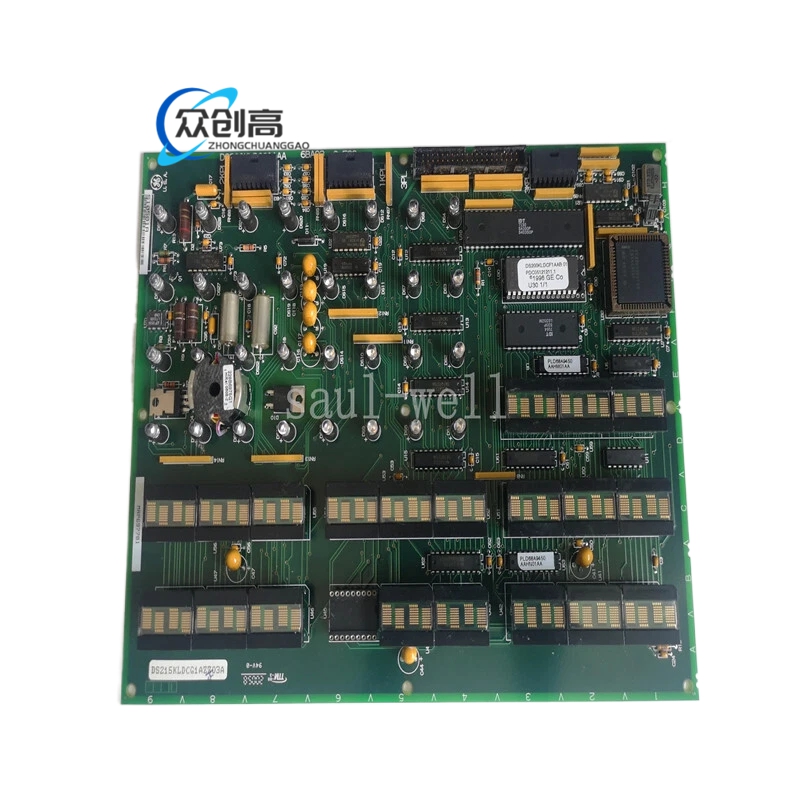
  • Ten diagnostic LEDs display health and error codes through flashing sequences
  • Modular connector supports daughter card integration, providing both signal and power connections for expanded functionality
  • Robust construction and precise analog handling
  • Supports continuous operation in industrial environments
  • Compatible with major PLC/DCS systems
Working Principle:​ The motherboard integrates a microprocessor and PROM modules to execute control algorithms. The 10 LEDs provide visual health status and error indication through specific flashing patterns. The modular connector allows daughter cards to attach via standoffs, receiving both signal and power connections.
Application Scenarios:​ Gas and steam turbine systems requiring Speedtronic technology; legacy system maintenance, repair, and replacement across industrial automation environments.

Installation Requirements:​ Integrates seamlessly with Mark V platforms.
Usage Notes:
  • When normal processing is taking place, the LEDs flash off and on in a clockwise direction from left to right
  • When an error code is generated, the LEDs flash in a specific sequence to display the error code
  • Due to the space requirements of daughter cards, it is standard practice to replace the board in the same location when performing replacements

You may also like