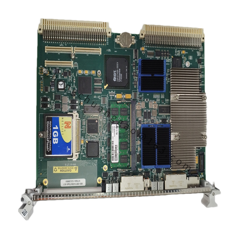
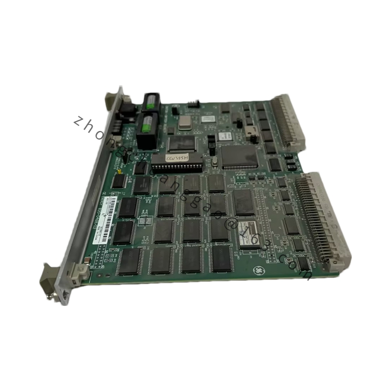
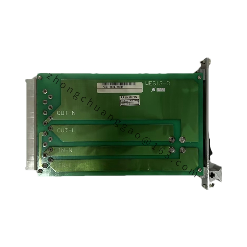
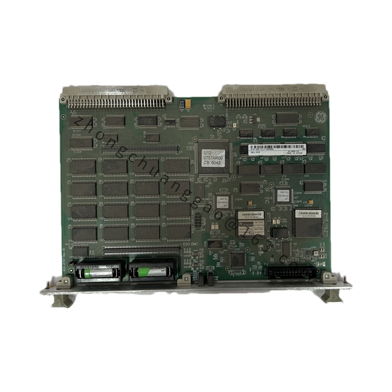
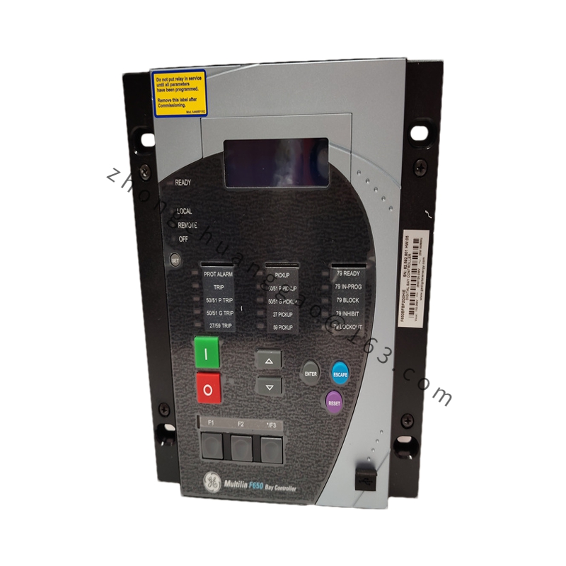
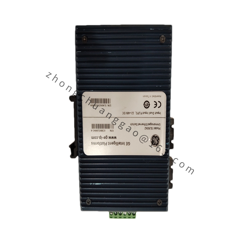
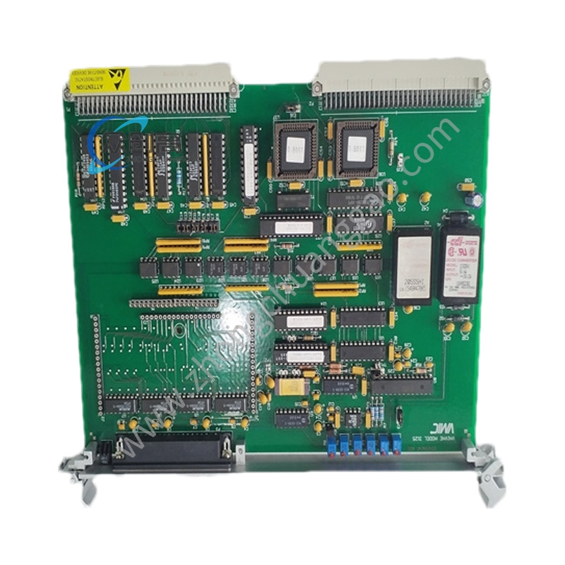
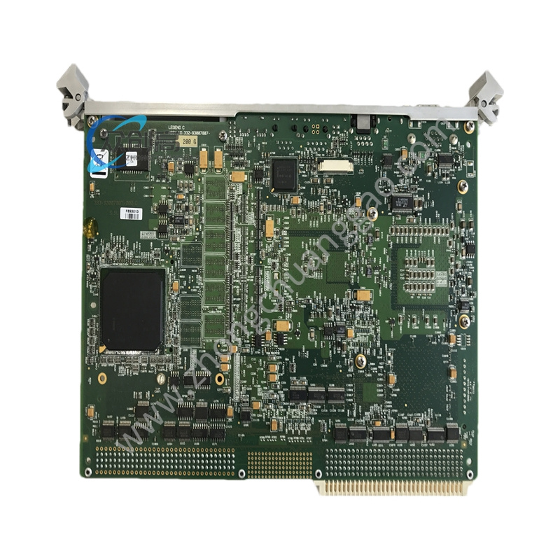
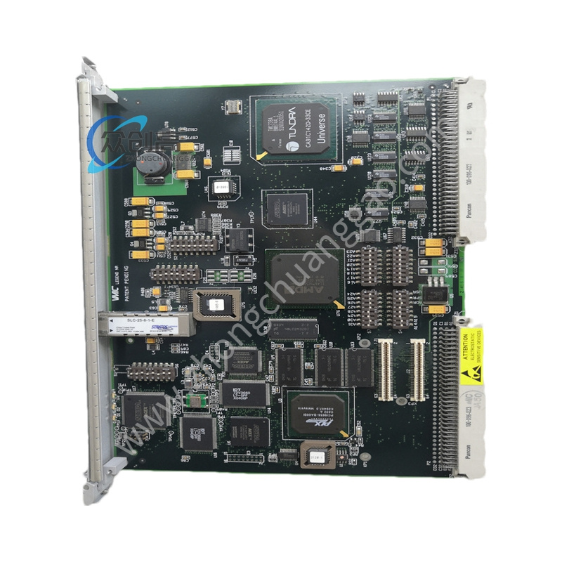
Product Introduction: The DS200UCIAG1A is the main printed wiring board (motherboard) at the heart of the Mark V Speedtronic system’s R-core. It provides the mounting slots and connection interfaces for daughter boards such as the UCPB CPU board, PANA ARCNET communication driver, GENI boards, and a PDAD hard disk drive, forming the central carrier for running turbine control logic.
Board Form Factor: Standard Mark V industrial printed circuit board format (approximately 11″ × 8″ × 1″)
Weight: Approximately 0.8 kg (1.7 lbs); shipping weight approximately 1 kg
Onboard Processor: 80196 microcontroller for translating fuel sliding pressure signals from the TCSA board
Key Connectors: UCPB mounting connector, GENI board connectors, PDAD hard disk connector, P14 fan connector
Jumpers: JP1 (manufacturing test only)
Test Points: TP1, TP2, TPI for diagnostics
Power: Low-voltage logic powered / bus regulated
Status: Obsolete / refurbished legacy product
Functional Characteristics: The onboard 80196 microprocessor converts fuel sliding pressure signals received from the TCSA board, then routes and writes them to the UCPB board where they are consumed by the control sequence program. The board integrates numerous ICs, vertical and right-angle connectors, resistor network arrays, jumper switches, capacitors, and resistors.
Application Scenarios: Central processor carrier in Mark V Speedtronic gas and steam turbine control systems; hosts the main processor (UCPB), communication drivers, and fuel pressure signal translation circuitry required for turbine control.
Working Principle: Daughter boards (UCPB, PANA, GENI) plug into the UCIA motherboard’s connectors. The onboard 80196 translates fuel pressure signals and passes them to the UCPB. The motherboard’s backplane and ribbon cable connections distribute power, data, and control signals across the R-core.
Installation Requirements:
Ensure all main rack power and external feeds are completely isolated, locked out, and tagged before handling.
Always wear an ESD wrist strap and handle the printed circuit board strictly by its edges.
Before power-up, verify that all mounted daughter cards (UCPB, PANA, GENI), internal ribbon cables, and backplane connectors are properly aligned and firmly seated.
Switch on main control rack power and observe system diagnostic LEDs to confirm proper boot initialization.
Usage Notes:
Live-insertion or hot-swapping of Mark V motherboards is strictly prohibited.
Routine maintenance involves checking edge connectors for oxidation, verifying secure ribbon cable attachments, and inspecting for dust accumulation.
Power-down sequence: safely halt turbine control operations via operator interface, turn off main rack power, wait for internal capacitors to fully discharge, then extract or service the board.