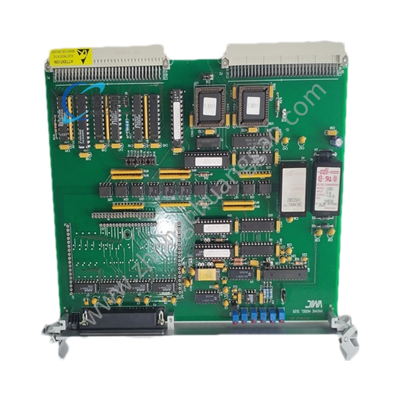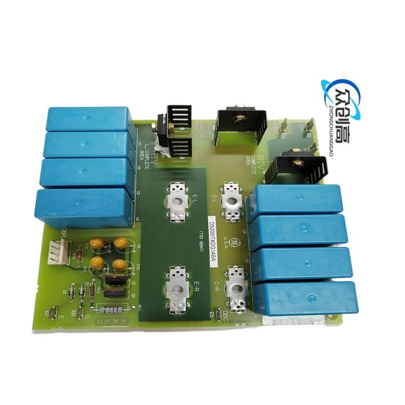


GE DS200TCTGG1AFF
Overview: The DS200TCTGG1AFF is a medium-format trip board developed by General Electric for the Mark V Speedtronic turbine control system. It serves as a primary safety component that processes trip signals and emergency stop commands, driving protective shutdown of fuel and steam trip solenoids when fault conditions such as overspeed or excessive vibration are detected. Available documentation identifies it as a Simplex Trip Board equipped with 21 plug-in Form-C (SPDT) relays for Mark V gas turbine control systems. Some supplier sources alternatively describe this part number as a thermocouple input terminal board — source documents vary on the exact configuration, so verification against site “As-Built” documentation is strongly recommended.
Detailed content
- Manufacturer: General Electric
- Model: DS200TCTGG1AFF
- System Series: Mark V Speedtronic
- Functional Acronym: TCTG (Trip Control Board)
- Product Type: Simplex / Medium Trip Board
- Total Relays: 21 plug-in relays (K1–K21), Form-C (SPDT) configuration
- Relay Mounting: Snap-in relays secured with metal straps
- Connectors: 3 × 50-pin (JLY, JLX, JLZ), 2 × 12-pin (JN, JM)
- Revision Code: 1AFF (functional rev A, rev F, artwork rev F)
- Operating Voltage: Compatible with AC 80–132 VAC and DC 105–140 VDC inputs
- Board Dimensions: ~12 × 21 × 2.5 cm
- Board Weight: 2.95 lbs (1.34 kg)
- Mounting: Vertical or horizontal rack mounting within Mark V control cabinet
- 21 independent relay-based trip paths for diverse fault conditions (overspeed, overtemperature, vibration, combustion instability)
- Triple Modular Redundant (TMR) support interface
- Non-redundant simplex design for applications where dual redundancy is not required
- Plug-in relay architecture allows easy maintenance and rapid replacement
- Isolation between control circuitry and field devices
- Normal PCB coating for protection against environmental contaminants
- Mark V boards are highly sensitive to ESD — always use a grounded wrist strap and ESD-protected workspace
- Power down the specific core where the board is located before removal/insertion
- Check hardware jumpers (J-connectors and BER pins) against the original board being replaced
- The “1AFF” revision must match the system’s software configuration
- Carefully align ribbon cables to avoid bent pins; ensure secure fastening to standoffs for reliable chassis ground
- Terminate solenoid and trip-loop wiring at dedicated terminal blocks; verify no stray wire strands cause shorts
- Perform a static trip test (turbine at zero speed) after installation to validate correct actuation