Digital guide

You are here:

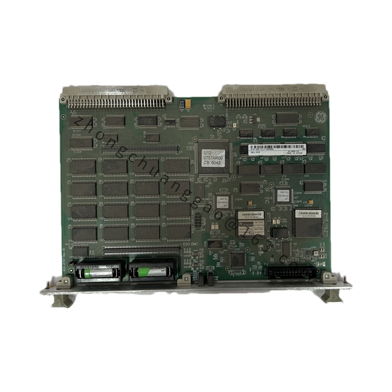
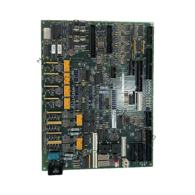
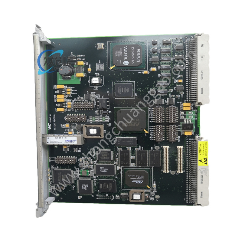
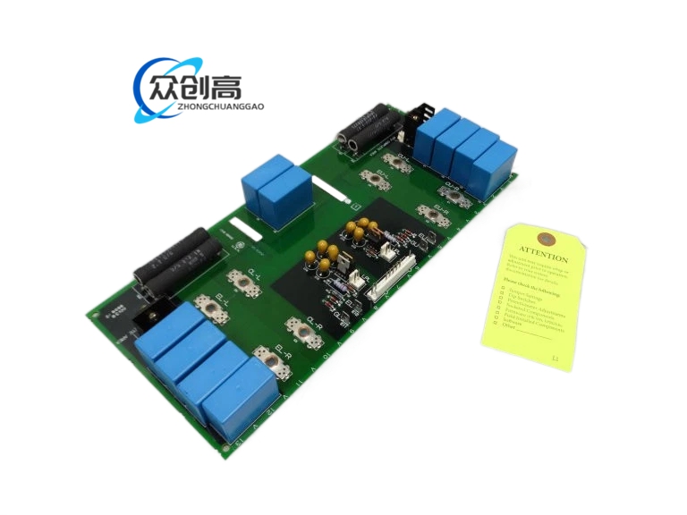
GE DS200TCQBG1B

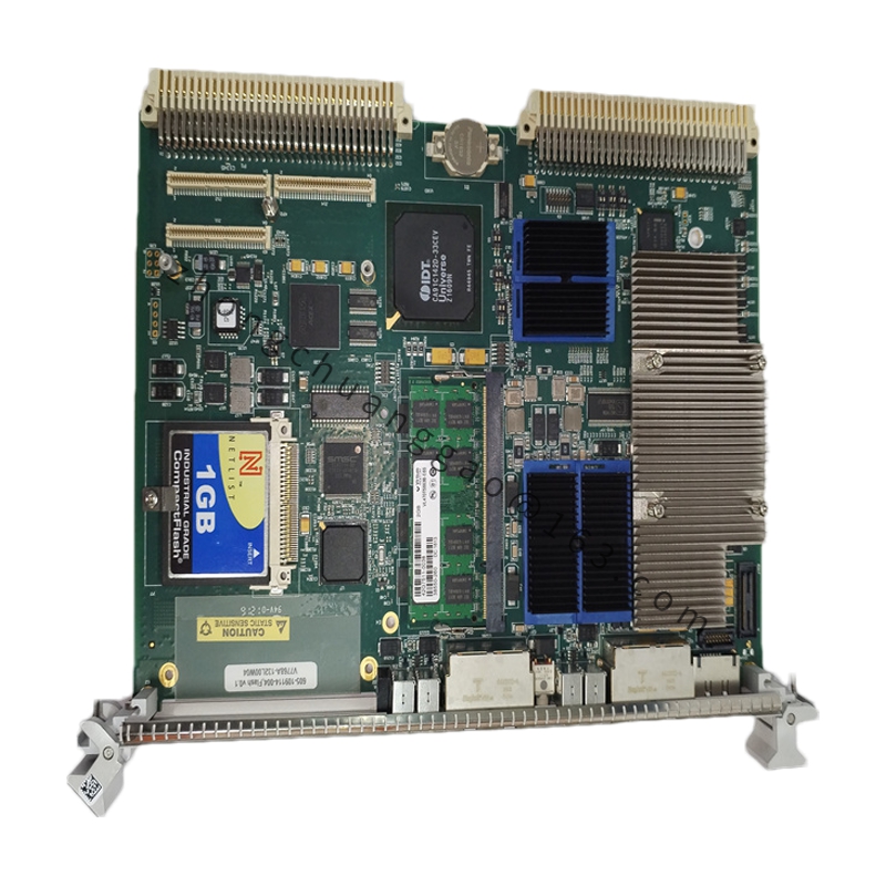
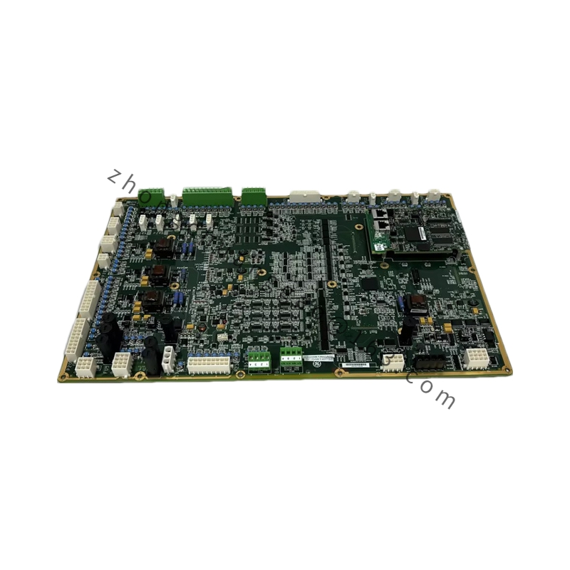
Product Name:​ GE DS200TCQBG1B – RST Extended Analog I/O Board (Mark V Turbine Control System)
Product Introduction:​ The DS200TCQBG1B is an RST extended analog I/O board for GE turbine control systems. It serves as a high-density analog interface, reading field signals (temperature, pressure, flow) from RST modules and sending control outputs to valves and positioners. The board provides 16 analog inputs and 8 analog outputs with 16-bit resolution, designed for reliable operation in GE RST turbine control applications.
Detailed content

Technical Specifications:
  • Power Supply:​ 24 V DC ±10%, 350 mA typical
  • Analog Inputs:​ 16 differential channels
  • Analog Outputs:​ 8 single-ended channels
  • Input Range:​ 0–10 V, ±10 V, or 4–20 mA
  • Output Range:​ 0–10 V or ±10 V
  • Resolution:​ 16-bit (input and output)
  • Accuracy:​ ±0.1% of full scale
  • Backplane Interface:​ 50-pin DIN
  • Power Connector:​ 6-pin terminal block
  • Dimensions:​ 24 cm × 18 cm × 5 cm
  • Weight:​ 0.85 kg
  • Energy Storage:​ Two electrolytic capacitors providing 220 µF at 35 V for output hold-up during 25 ms power interruptions
  • Construction:​ Six-layer PCB with separate analog and digital grounds
  • Operating Temperature:​ -10 °C to +55 °C
Internal Components:
  • 2 AD converters (8-channel each)
  • 1 DA converter (8-channel)
  • 1 DSP (32-bit)
  • 16 analog conditioners
  • 8 output drivers
  • 24 precision resistors
  • 18 capacitors
Key Features:
  • 16 differential analog inputs + 8 single-ended analog outputs
  • 16-bit resolution for both input and output
  • Output hold-up during brief voltage dips (25 ms)
  • Separate analog/digital ground planes to minimize noise
  • M3 screw mounting at four corners
Application Scenarios:​ High-density analog interface for GE RST turbine control systems — connecting field sensors and actuators to the turbine control system, reading temperature/pressure/flow signals and driving control outputs to valves and positioners.
Installation Notes:
  • Use M3 screws for the four mounting holes
  • Draws 300 mA typical current from 24V DC supply
  • Each output channel can drive loads up to 20 mA maximum
  • Shielded cables recommended for all analog field connections

You may also like