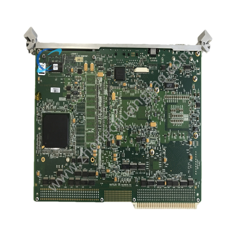
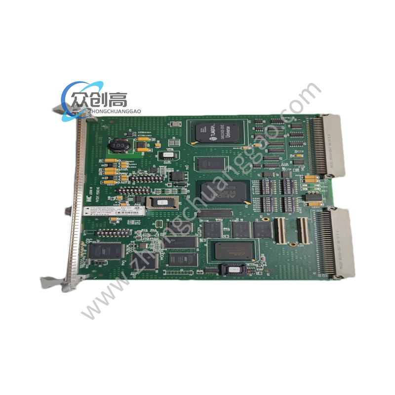
-
Technical Specifications (based on the documented TCQAG1BHF; G2BHF carries the same functional architecture with later artwork revision):
-
Channels: 8 differential analog I/O, ±10 V full scale
-
Accuracy: 0.1 % full scale
-
Isolation: 2500 Vrms channel‑to‑ground
-
Termination: 2 × 10⁷‑point screw blocks (214 terminals total)
-
Connectors: 4 × 34‑pin and 2 × 40‑pin headers (J1‑J6)
-
Jumpers: 6 Berg jumpers for range / filter / redundancy routing
-
LEDs: 6 status LEDs (power, comm, fault per pair)
-
Power supply: +5 V & ±15 V from back‑plane; field loops self‑powered
-
Operating temperature: –40 °C to +70 °C
-
Dimensions / weight: ≈ 203 × 61 × 25 mm (or 330 × 280 × 25 mm per alternate source), 0.25‑0.45 kg
-
Protection: IP20 (rack) – IP65 front‑panel option
-
Redundancy: TMR‑capable (works in TCQA/TCQB triple‑redundant group)
-
Functional Features: Collapses three DIN‑rail terminal strips, 2500 V isolators, and pull‑down resistors into a single 6‑inch card; supports 4‑20 mA, thermocouple, LVDT/LVDR, vibration, pulse, voltage, relay‑driver, and generator/line signals; TMR‑ready for high‑availability turbine‑control applications.
-
Application Scenarios: Mark V or Mark VI Speedtronic racks on gas‑turbine (e.g., 7EA, 9F) and steam‑turbine installations where multiple analog field signals must be interfaced with the turbine‑control processor.
-
Structural & Material Characteristics: Multi‑layer PCB with edge connector to Mark V/VI back‑plane; screw‑terminal blocks for field wiring; Berg jumpers for configuration; on‑board diagnostic LEDs; optional IP65 front cover.
-
Working Principle: Field analog signals are landed on the screw terminals, scaled/conditioned by on‑board circuitry, isolated at 2500 Vrms, and passed via the back‑plane connectors to the Mark V/VI processor; jumper settings determine range, filtering, and redundancy routing.
-
Installation Requirements: Insert the board into the correct Mark V/VI rack slot; land field wires on the two screw blocks (torque to 0.8 Nm); set the six Berg jumpers per GEI‑100161 jumper map; connect the 34‑pin/40‑pin headers to the appropriate I/O cores; ensure back‑plane power (+5 V, ±15 V) is present.
-
Usage Precautions: Read the jumper map from the component side – flipping the board can mis‑align jumpers and halve the input range; use a calibrated screwdriver and tug‑test every wire; keep the cabinet door closed (IP20) to avoid corrosion; always de‑energize the rack before insertion/removal; verify that the exact suffix (G2BHF) matches the system’s required TCQA revision before replacement.