Digital guide

You are here:

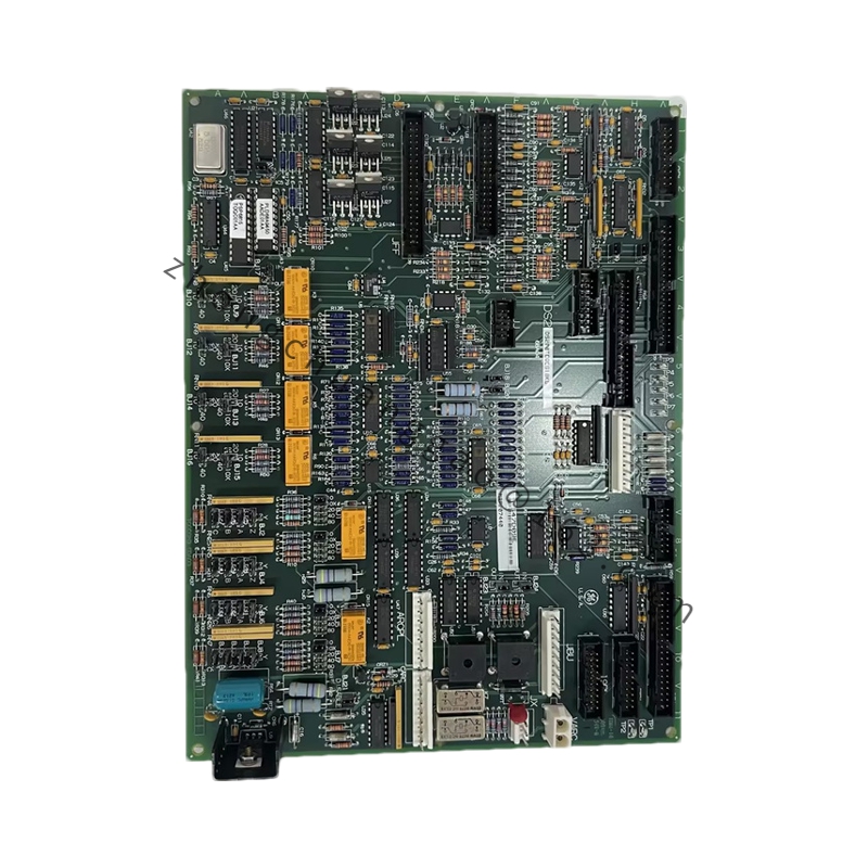
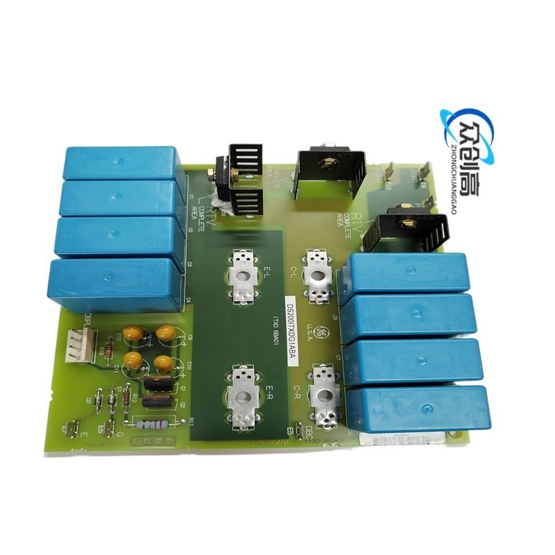
GE DS200TCEBG1AAB

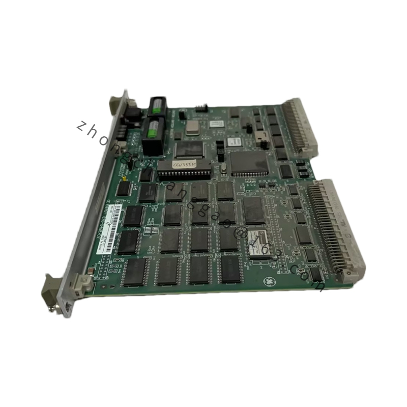
GE DS200TCEBG1AAB is a Turbine Control Emergency Trip Board (TCEB) that serves as the dedicated safety layer in legacy GE Mark II / Mark III turbine control architectures, executing emergency shutdown logic and monitoring critical trip circuits.
  • Technical Specifications
    • Input Voltage: 24 V DC nominal (18–32 V range)
Detailed content

    • Logic Type: Positive logic (High = True)
    • Output Relays: 3 Form-C (SPDT) heavy-duty relays
    • Relay Contact Rating: 5 A @ 250 V AC / 30 V DC (resistive)
    • Trip Response Time: <10 ms
    • Backplane Isolation: 10 MΩ @ 500 V DC
    • Operating Temperature: -20°C to +60°C
    • Dimensions: 233 mm (H) × 160 mm (W) × 40 mm (D)
    • Mounting: Eurocard rack mount, 6U-compatible
  • Functional Characteristics
    • Hardwired isolation of emergency stop signals from standard process logic
    • Direct relay cut-off of fuel and steam valves for fail-safe state
    • Redundant monitoring circuits detect internal failures before safety is compromised
    • MTBF exceeds 100,000 hours with stable 20–28 V input
  • Structural Features
    • Standard Eurocard form factor for 19-inch GE Mark II/III racks
    • Front-panel screws and rear guide rails for secure mounting
    • Status LEDs: “Power” (green) and “Trip Ready” / “Trip” (red)
  • Application Scenarios
    • Legacy GE Mark II and Mark III turbine control systems
    • Emergency shutdown (ESD) for gas and steam turbines
    • Safety-critical turbine protection where fail-safe hardwiring is required
  • Installation Requirements
    • Install in Slot 4 or 5 of TC rack per system wiring diagram
    • Power down and lockout/tagout the 24 V DC supply before installation
    • Use stranded wire (18–22 AWG) with ferrules for terminal connections; torque to 0.5–0.6 N·m
    • Inspect backplane pins for bends before insertion
    • Slide in smoothly until ejector locks engage; secure with four M4 screws torqued to 1.2 N·m
  • Usage Notes
    • Not compatible with Mark VIe systems; using TREG or VTUR packs instead for VIe
    • Input voltage must remain stable within 20–28 V DC “sweet spot”
    • Source only from tested surplus or refurbished stock with test reports; untested boards pose extreme risk
    • Verify “Power” LED is solid green and “Trip Ready” is illuminated at power-on

You may also like