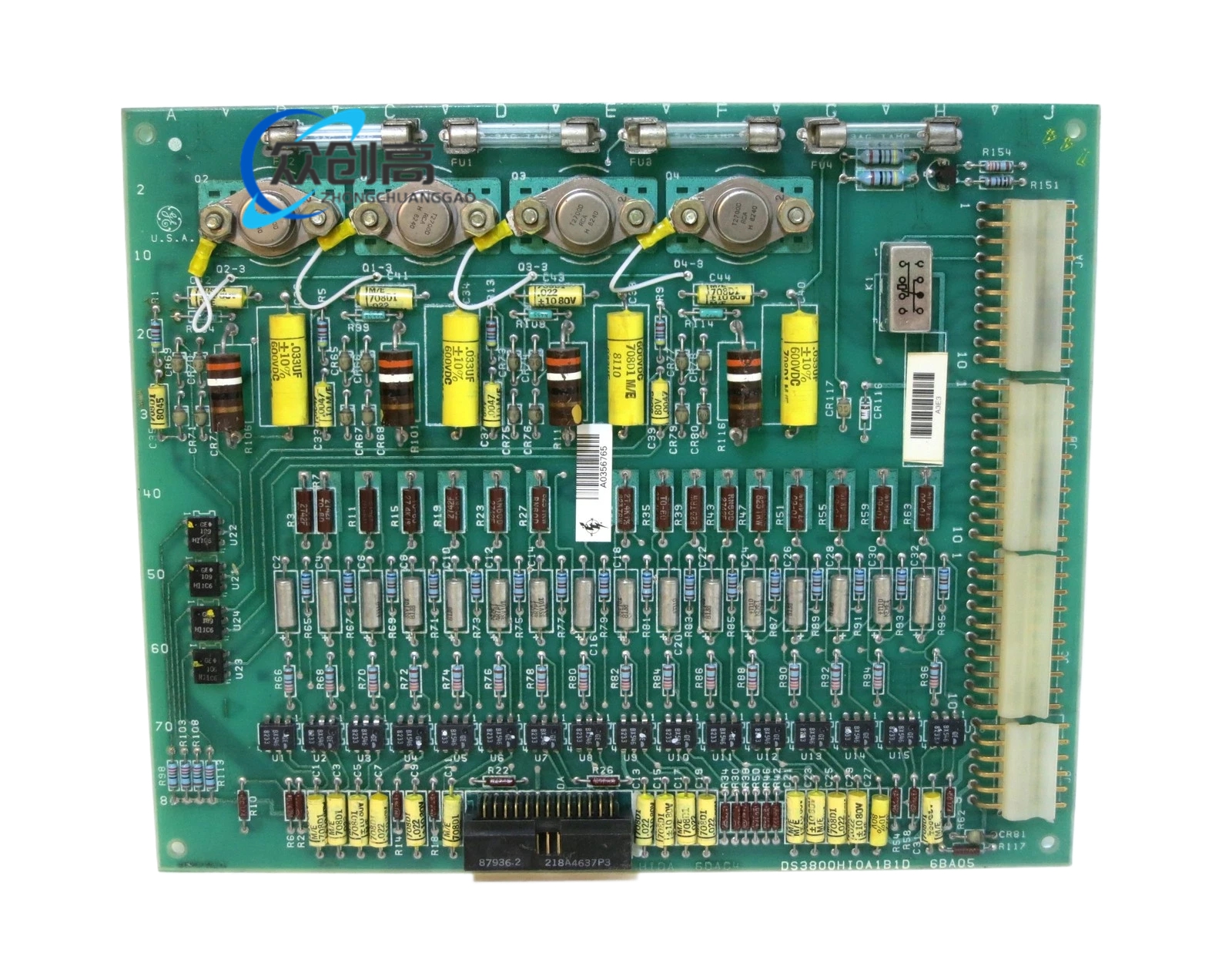
GE DS200TCEAG1BSF
Product Name: GE DS200TCEAG1BSF Emergency Overspeed Board (Mark V Turbine Control)
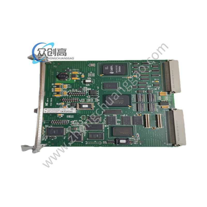
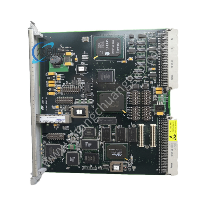
Product Overview: The DS200TCEAG1BSF is a protective processor board for GE’s Speedtronic Mark V turbine control system. It forms part of the Triple Modular Redundant (TMR) protection architecture, with three boards (X, Y, Z) providing high-speed emergency overspeed protection for gas and steam turbines. The board monitors shaft speed via magnetic pickups, processes flame detector signals, and manages automatic synchronization permissives.
Detailed content
Technical Specifications:
- Model Number: DS200TCEAG1BSF
- Product Series: Mark V Turbine Control System
- Functional Acronym: TCEA – Emergency Overspeed Board (Protective Processor)
- Core Location: Protective Core; roles X, Y, or Z
- Boards per System: 3 (X, Y, Z) for TMR protection
- Overspeed Inputs: High-pressure and low-pressure shaft speed (magnetic pickups) via PTBA/TCEB
- Flame Detection Inputs: UV flame detector signals via PTBA/TCEB
- Flame Detector Power Output: 335 V DC (via JW connector)
- Automatic Synchronization: Bus and generator voltage/frequency inputs; speed and voltage matching; permissive breaker closure
- Trip Outputs: Emergency trip signals to TCTG board via JL connector; relay driver level voting (2/3)
- Communication: IONet (Ethernet-based) via JX1/JX2 daisy-chain; connects to TCQC and TCDA
- Power Supply: Supplied from core via J7 connector
- Configuration Jumpers: J1–J31 (factory test, IONet termination, IONet address, overspeed trip frequency, forced trip, stall timer)
- IONet Address: J4, J5, J6 (3-bit binary) – defines board as X, Y, or Z
- Overspeed Trip Settings: Hardware jumpers J8–J27 confirm software-defined trip frequencies for HP and LP shafts
- Stall Timer: Enabled by J30 – watchdog timer for communication loss protection
- Operating Temperature: 0°C to 50°C (typical Mark V cabinet)
- Storage Temperature: -40°C to +85°C
- Humidity: 5% to 95% non-condensing
- Certifications: UL, CSA, CE (as part of Mark V system)
Functional Features:
- High-speed overspeed monitoring and emergency trip
- Flame detection signal processing with intensity calculation
- Automatic synchronization check function
- Triple Modular Redundancy (TMR) with 2/3 voting
- IONet communication loss detection via stall timer
- No routine calibration required
Performance Parameters:
- 2/3 voting relay driver for trip decisions
- Watchdog stall timer protects against communication loss
- Operating range 0°C to 50°C for cabinet installation
Material & Structural Characteristics:
- PCB-based protective processor with 30 configuration jumpers
- Multiple bayonet connectors (JW, JL, JX1, JX2, J7) for integration
- Part of Mark V system certified to UL, CSA, CE
Working Principle: The board receives shaft speed signals from magnetic pickups and compares them to hardware-jumper-confirmed trip frequencies. If overspeed is detected, it initiates an emergency trip via the TCTG board using 2/3 voting among the three (X, Y, Z) redundant boards. It simultaneously processes flame detector inputs and provides automatic synchronization permissives. The stall timer acts as a watchdog to trigger trips on IONet communication loss.
Installation Requirements:
- Install in Mark V protective core with proper slot assignment (X, Y, or Z)
- Set IONet address jumpers (J4–J6) to define board role
- Configure J8–J27 to confirm software-defined overspeed trip frequencies
- Enable J30 stall timer for communication loss protection
- Ensure proper seating of all bayonet connectors (JW, JL, JX1, JX2, J7)
Usage Notes:
- All digits and letters in the part number are significant; order using complete part number
- Periodic visual inspection for dust, corrosion, or loose connections
- GE may substitute later compatible revisions with backward compatibility assured
- No routine calibration required