Skip to content
+86 18060908697
3549711439@qq.com
Clear
Search
Home
About us
Shop
ABB
GE
Bently
Emerson
Foxboro
Honeywell
Ics Triplex
Motorola
Woodward
News
Company News
Industry news
Contact
Digital guide
You are here:
Home
GE
GE DS200TCEAG1AGB
GE DS200TCEAG1AGB
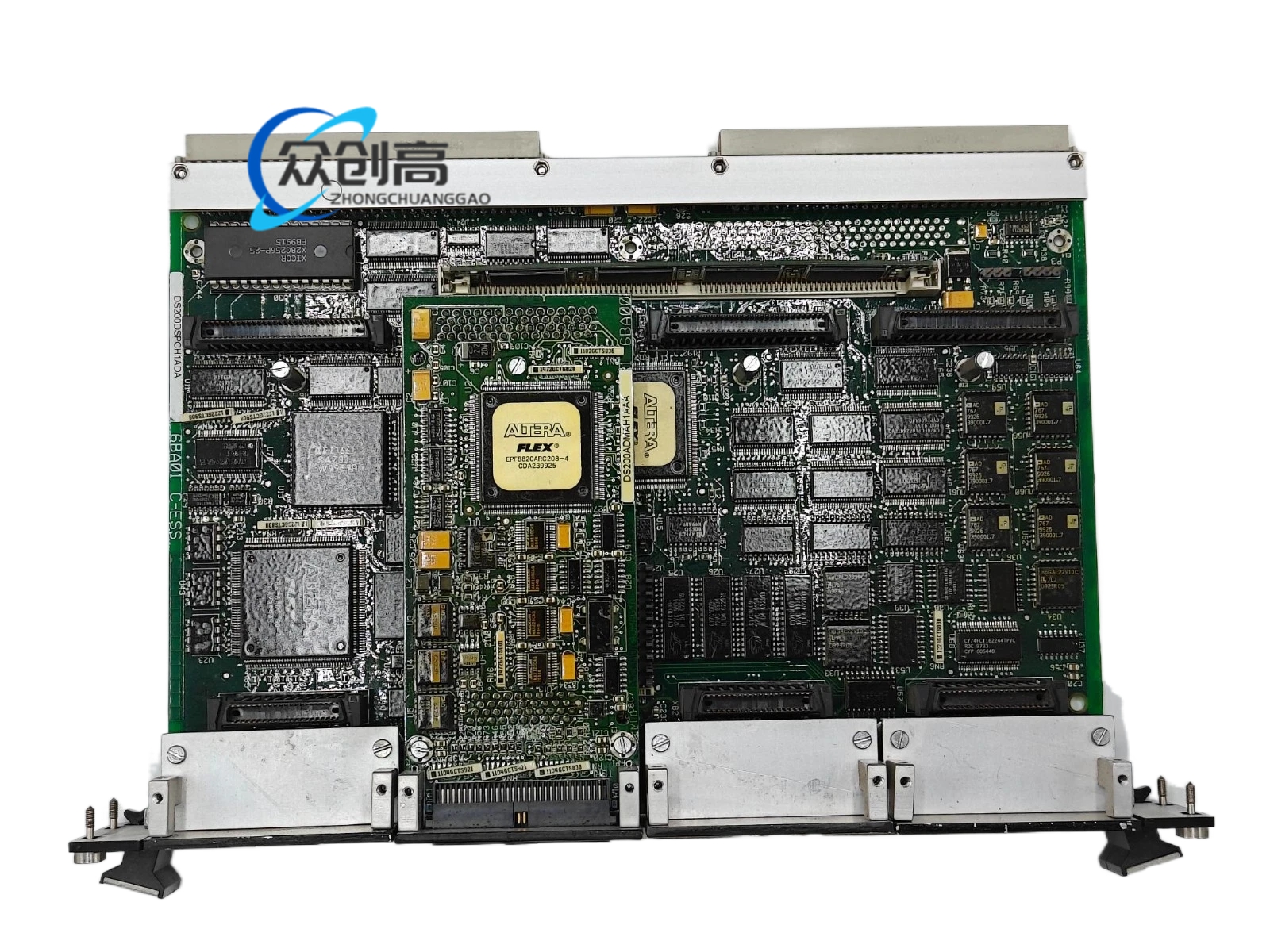
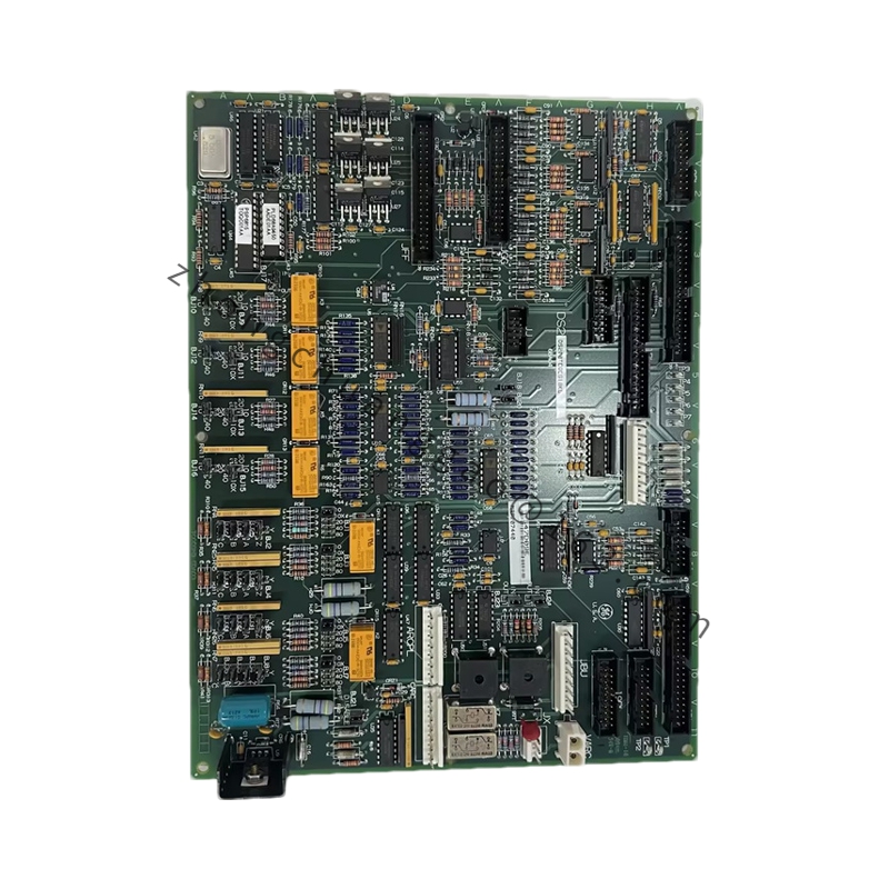
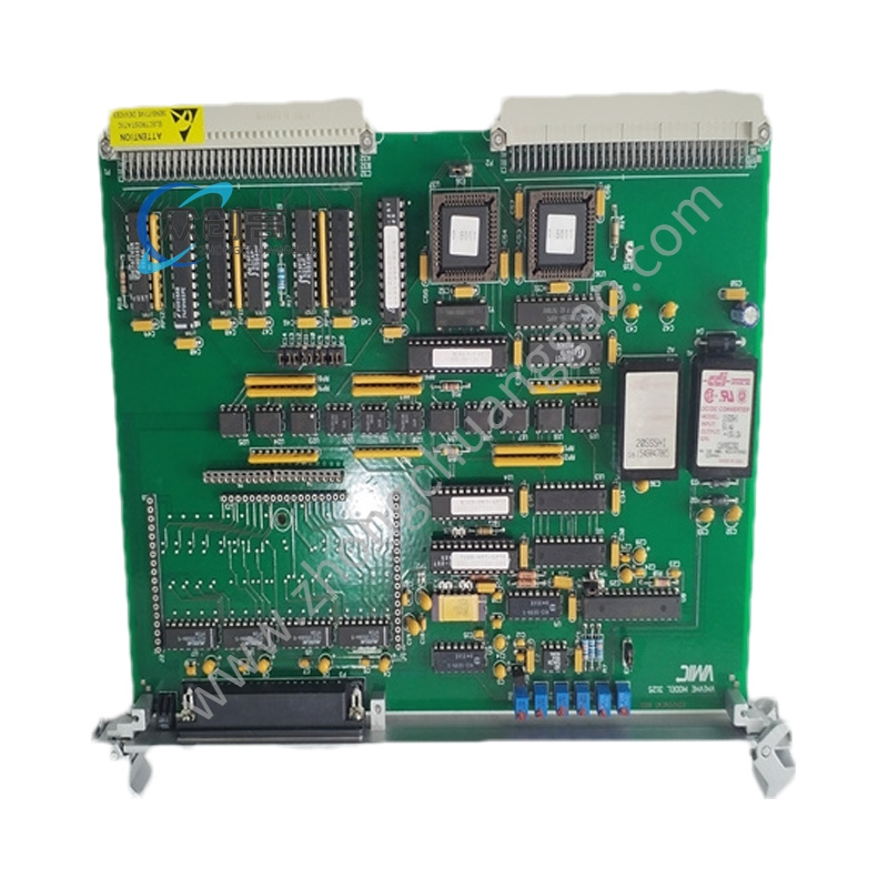
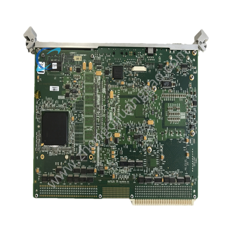
GE DS200TCEAG1AGB is an Emergency Overspeed Board designed for the GE Mark V series of turbine control systems, providing real-time overspeed detection and emergency trip action to safeguard against unexpected high-speed events.
Technical Specifications
Series: Mark V
WhatApp
WeChat
Detailed content
Function Revision: J; Artwork Revision: E; Primary Functional Revision: B; Secondary Functional Revision: G
Processor: High-performance microcontroller
Memory: 8 Kb RAM, 8 Kb ROM
Operating Temperature: -40°C to +60°C
Input Voltage Range: 24 V DC to 60 V DC
Output Signal: Relay contact
Communication: RS-485
Board Size: 150 mm × 100 mm
Connectors: J7 (PD Core Power Distribution), JK (TCEB Board Signal), JL (TCTG Board Trip Signal), JW (TCEB Board Flame Detection), JX1 & JX2 (daisy-chained IONET)
Certifications: UL, CE, ISO 9001
Functional Characteristics
Real-time monitoring of shaft speed with rapid overspeed detection
Immediate corrective trip action upon detection of rapid speed changes
Dual-redundant trip circuits for SIL3-compliant safety
Precision overspeed detection with 0.1% RPM accuracy
Flame detection and automatic synchronization signals processing
High and low shaft speed monitoring
Structural Features
Advanced epoxy resin coating for corrosion and environmental hazard resistance
High-grade aluminum material for strength and heat dissipation
Three TCEA boards (X, Y, Z processors) constitute the Protective Core P1
Signals from X-position board transmitted via JX1 to STCA board in R1 core over IONET
Application Scenarios
Gas turbine protection and emergency shutdown
Steam turbine safety systems
Power generation critical control
Compatible with Mark V / Vi / Vie, EX2100e excitation control, HMI/SCADA integrations
Installation Requirements
Install in the Protective Core P1 of Mark V LM series turbine control systems
Connect JX1 and JX2 for daisy-chained IONET communication
Properly seat J7, JK, JL, and JW connectors per wiring diagram
Ensure input voltage within 24–60 V DC range
Usage Notes
Maintain operating temperature within -40°C to +60°C
Military-grade connectors rated for 10,000+ mating cycles
Verify jumper and configuration settings match system requirements before power-up
Handle with ESD protection; epoxy coating provides environmental resistance but board remains static-sensitive
You may also like
GE 8521-HC-MT
GE 8521-EB-MT
GE 8502-BI-DP
GE 605-109114-004
GE 369-HI-R-M-0-E-0
GE 369-HI-R-M-0-0-0-E
GE 239-RTD-AN
GE IS200WETAH1AGC
GE DS200TCQCG1AJD
GE SLN080 IC086SLN080-A
GE VMVIVME-3125
VMIVME-7807
Go to Top
Home
About us
Shop
ABB
GE
Bently
Emerson
Foxboro
Honeywell
Ics Triplex
Motorola
Woodward
News
Company News
Industry news
Contact
phone:
18060908697
Email:
3549711439@qq.com
Clear
Search