Skip to content
+86 18060908697
3549711439@qq.com
Clear
Search
Home
About us
Shop
ABB
GE
Bently
Emerson
Foxboro
Honeywell
Ics Triplex
Motorola
Woodward
News
Company News
Industry news
Contact
Digital guide
You are here:
Home
GE
GE DS200TCDAH1BJE
GE DS200TCDAH1BJE
GE DS200TCDAH1BJE is a Digital Input/Output Board designed for GE Speedtronic Mark V series turbine control systems, managing the flow of digital (discrete) signals between the main control system and field equipment over IONET communication.
Technical Specifications
Series: Mark V (TCDA)
WhatApp
WeChat
Detailed content
Communication: IONET (Ethernet-based) via JX1 or JX2 shielded twisted pair
Communication Redundancy: Dual ports (JX1 and JX2)
Contact Inputs: Up to 32 per DTBA/DTBB terminal board configuration
Contact Outputs: Up to 16 relays per TCRA configuration
Input Conditioning: Debounce filtering, change-of-state detection, time-tagging
Input Inversion: Software-configurable via I/O Configuration Editor
Power Supply: +5 V DC, ±15 V DC (from TCPS board via JP connector)
IONET ID: 3-bit binary setting via J4, J5, J6 jumpers
Stall Timer: Enabled via J7 jumper to protect outputs on IONET communication failure
Hardware Jumpers: 8 total (J1–J8) for termination, IONET ID, stall timer, and factory test
Operating Temperature: 0°C to 50°C
Storage Temperature: -40°C to +85°C
Humidity: 5% to 95% non-condensing
Agency Approvals: UL, CSA, CE (as part of Mark VI system)
Functional Characteristics
Acquires digital contact input signals from DTBA/DTBB terminal boards via JQ and JR 50-pin connectors
Conditions and time-tags input signals before transmitting to main processor
Manages contact output signals to TCRA boards for relay and solenoid actuation
Communicates processed signals over IONET to the rest of the control system
Typically installed in digital I/O cores (Q11 and Q51) of Mark V LM turbine control systems
Structural Features
Two 50-pin ribbon connectors (JQ, JR) for terminal board interface
Two 3-pin connectors (JX1, JX2) for IONET communication
One side-visible LED (CR9) — green when powered, flashing during processing
Block of 10 LEDs for status and diagnostic feedback
8 hardware jumpers (JP1–JP8) for configuration
Conformal coating for harsh industrial environment protection
Application Scenarios
Mark V Speedtronic turbine control systems
Digital contact signal management for gas and steam turbines
Industrial automation requiring discrete I/O over IONET
Relay and solenoid actuation control
Installation Requirements
Install in Q11 and Q51 digital I/O cores of Mark V LM control system
Route 50-pin ribbon cables carefully to minimize EMI exposure
Configure JP1–JP8 jumpers to match the replaced board’s settings
Set IONET ID via J4, J5, J6 to avoid address conflicts
Power supplied by TCPS board via JP connector
Usage Notes
Jumper settings MUST be correctly matched to the original unit when replacing
CR9 LED must be green and flashing to confirm proper power and processing
Use ESD protection during handling
Stall timer (J7) protects outputs if IONET communication fails — enable per system requirements
You may also like
GE 8502-BI-DP
GE 04220FL11232A
GE 469-P1-HI-A20-E
GE 369-HI-R-M-0-E-0
GE 369-HI-R-M-0-0-0-E
GE 369B1860G0030
Triconex 2201
GE WES51202340-21006
GE IS200WETAH1AGC
GE D20 EME27-APR-13
GE 239
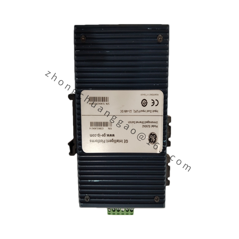
GE SLN042 IC086SLN042-A
Go to Top
Home
About us
Shop
ABB
GE
Bently
Emerson
Foxboro
Honeywell
Ics Triplex
Motorola
Woodward
News
Company News
Industry news
Contact
phone:
18060908697
Email:
3549711439@qq.com
Clear
Search