GE DS200TBQDG1AEE
Product Name: Mark V RST Extension Analog Termination Board
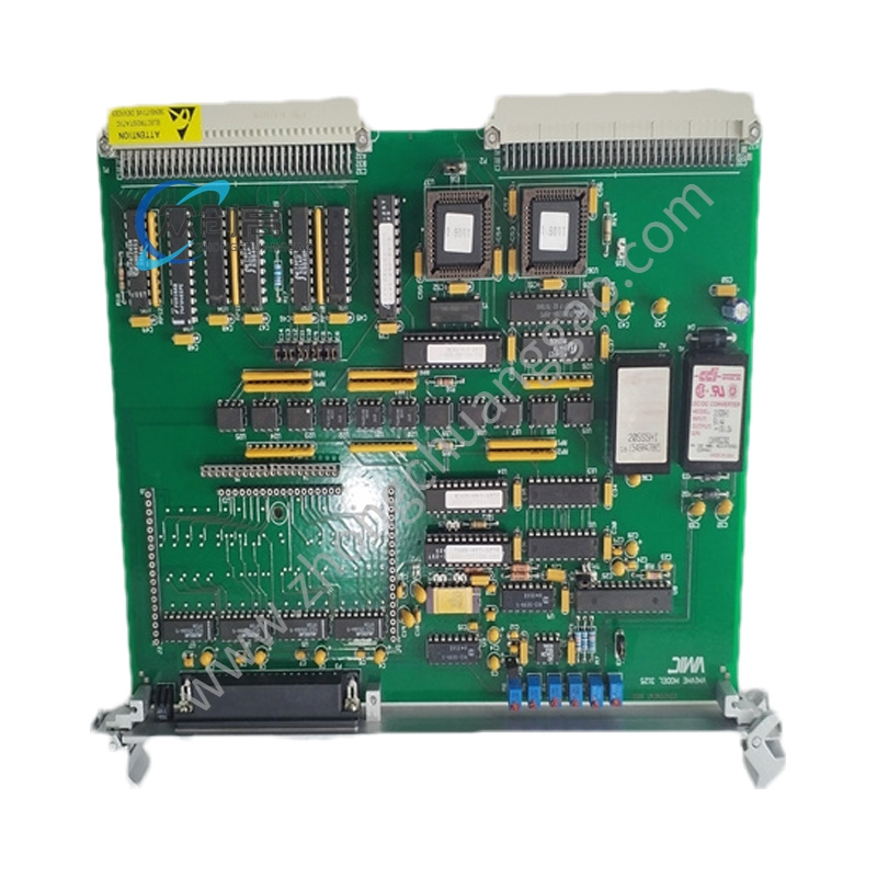
Product Introduction: The DS200TBQDG1AEE is a Mark V Speedtronic analog termination board that provides a high-density field-wiring interface for analog and transducer signals — including Proximitor (proximity probe), LVDT (Linear Variable Differential Transformer) inputs, and milliamp outputs. It serves as the signal bridge between field sensors/actuators and the Mark V rack-mounted control modules.

Detailed content
Technical Specifications:
- Manufacturer: General Electric
- Series: Mark V DS200
- Board Type: Analog Termination Board (RST extension)
- Terminal Blocks: 2 blocks, each with 107 terminals (signal wires)
- Connectors: 3 × 34-pin connectors for signal routing to Mark V modules
- Test Points: 3 (TP1, TP2, TP3) for calibrated circuit testing
- Jumpers: BJ1, BJ2 for field-configurable signal processing
- Signal Types Supported: Proximitor, LVDT, milliamp (4–20 mA) analog
- Voltage: 24 VDC
- Current Handling: 1 A per channel
- PCB Coating: Standard (insulation and heat dissipation)
- Dimensions: 170 mm × 90 mm × 5 mm
- Weight: 0.15 kg
- Operating Temperature: –40 °C to +70 °C
- MTBF: Exceeds 200,000 hours
Functional Features:
- Voltage-limiting hardware protects against electrical fluctuations, ensuring stable signal integrity
- Jumper-configurable (BJ1, BJ2) for matching different signal types
- High-density 107-terminal blocks allow complex I/O setups in a compact footprint
- Broad operating temperature range (–40 °C to +70 °C) for extreme industrial environments
- Higher current handling (1 A) compared to similar analog termination boards (typically 0.8 A)
Application Scenarios: Gas and steam turbine control systems for signal acquisition from proximity probes (vibration, thrust) and LVDTs (valve position); renewable energy wind turbine monitoring; industrial process control and data acquisition.
Installation Requirements:
- Handle with ESD protection — the board contains sensitive analog conditioning components
- Set jumpers BJ1 and BJ2 according to the signal type defined in engineering drawings before wiring
- Securely attach the 3 × 34-pin ribbon connectors to the corresponding Mark V module backplane ports, ensuring locking latches engage fully
- Terminate field wires on the 107-position terminal blocks, observing correct polarity for Proximitor and LVDT signals
Usage Precautions:
- Always de-energize field wiring and verify zero voltage before terminating or servicing
- Use calibrated instruments at test points TP1–TP2–TP3 for circuit verification
- When disconnecting ribbon cables, grasp the connector body firmly — do not pull on the cable wires, as this can damage the 34-pin contacts
- Verify the board’s –40 °C to +70 °C operating range matches the installation environment; exceeding this range will degrade MTBF