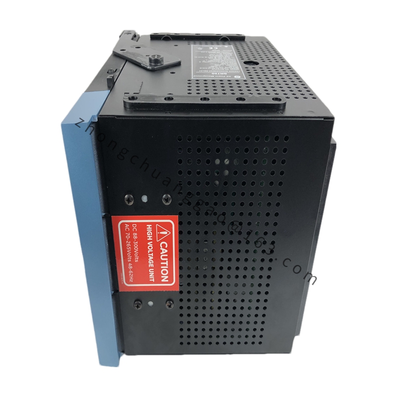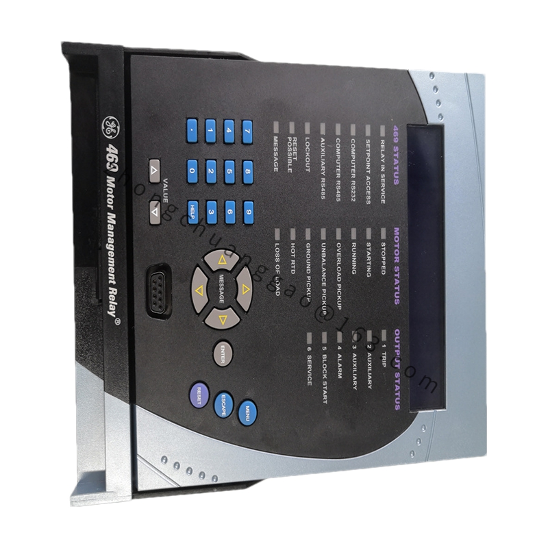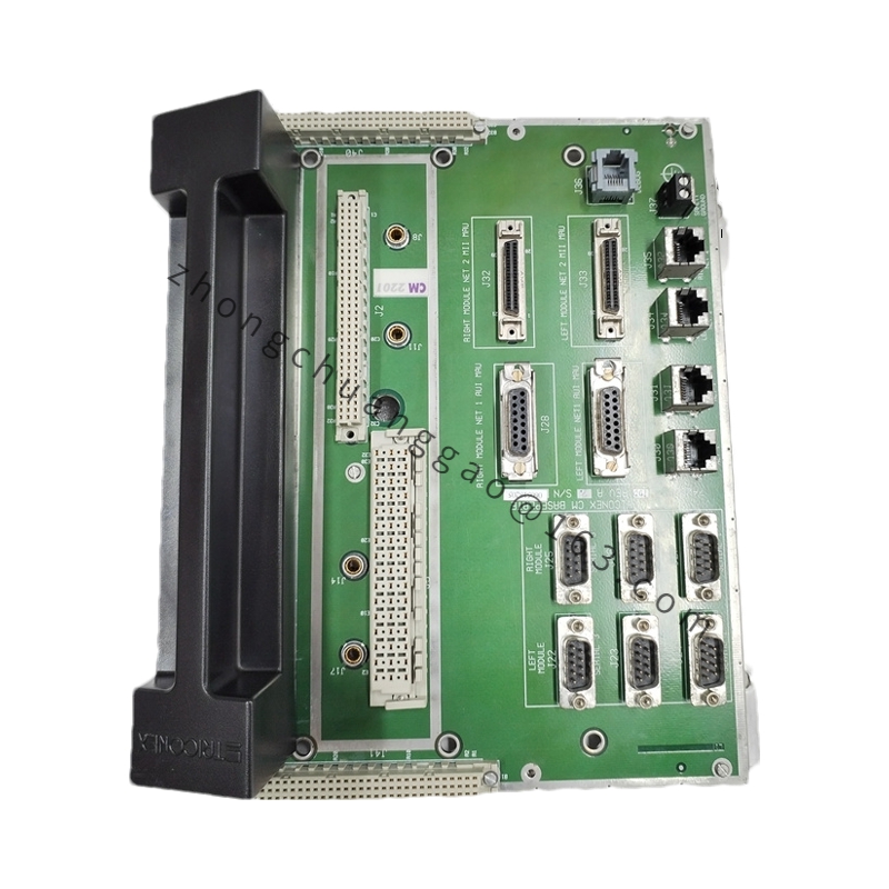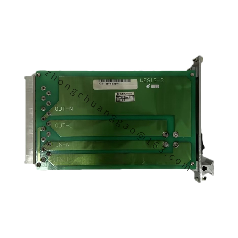
GE DS200SPCBG1A
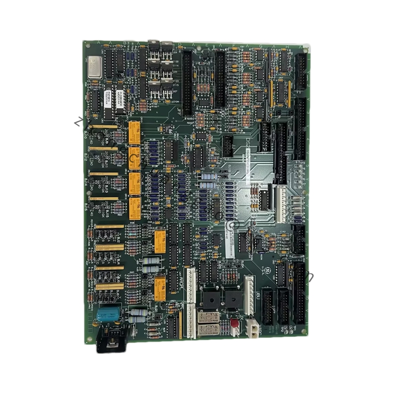
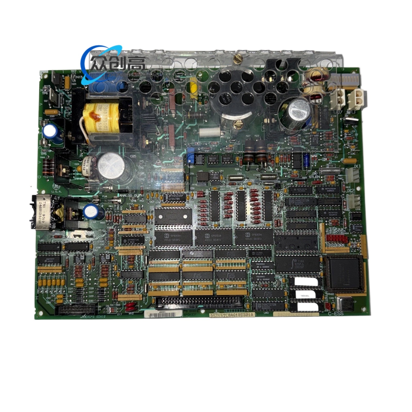
Product Name: Mark V Multi-Bridge Signal Processing Board (SPCB)
Product Introduction: The GE DS200SPCBG1A is a multi-bridge signal processing card for GE’s Mark V DS200 drive system. It acts as a “signal hub” between the SDCC main processor and MBI-IA bridge boards, handling encoder feedback, analog scaling, and fiber-optic gate timing for multi-bridge parallel drive applications.
Detailed content
Technical Specifications:
-
Series: Mark V DS200
-
Type: Multi-bridge signal-processing card
-
Power Requirements: +5 V DC @ 6 A (logic), +28 V DC (field power)
-
Operating Temperature: -30 °C to +65 °C
-
Connectors: 27 bayonet-type firing outputs, 34-pin & 9-pin D-Sub I/O, fiber ST ports for encoder & bridge-bridge communications
-
Signal Types: Encoder differential TTL, ±10 V analog process control, 820 nm fiber gate pulses
-
Isolation: 1500 V DC channel-to-ground; 2.5 kV optical on fibers
-
Functions: Sends encoder feedback to SDCC; Converts 4–20 mA / ±10 V process signals to 5 V TTL for SDCC; Fiber-optic transmit/receive for bridge-to-bridge sync & master-master systems
-
Encoder Input Range: 5–15 V DC (configurable via SW1 DIP switch)
-
Adjustable Elements: 1 DIP switch (SW1), 6 potentiometers (P1–P6), Berg-type jumpers
-
Dimensions: ≈ 11 × 8 in (279 × 203 mm)
-
Weight: 0.25 lbs (≈ 0.11 kg)
-
PCB Coating: Standard industrial coating resisting dust, moisture, and corrosion
-
Manual: GEI-100172A
Key Features: Dual-role signal processing & communication — integrates encoder feedback processing with fiber-optic bridge-to-bridge communication, reducing system complexity by 40% and failure points by 60% compared to competitor boards requiring separate modules. Configurable encoder compatibility via SW1 DIP switch allows on-site adjustment in 10 minutes (vs. 3–5 days factory recalibration for legacy boards). Fiber-optic network capability boosts communication speed by 10× compared to legacy copper links while eliminating EMI. Zero board removal calibration: 6 potentiometers enable online gain and bias adjustment. Hardcore status decoding: PAL circuit automatically generates up/down/marker pulses, encoder disconnection alarm within 10 µs.
Working Principle: The board takes motor encoder input on the front end, duplicates and transmits the signal down fiber to multiple bridges for phase synchronization. It scales 4–20 mA armature current feedback to 5 V TTL that the SDCC A/D can process, and handles fiber-optic gate timing for synchronized multi-bridge operation.
Application Scenarios: Gas/steam turbine starting frequency converters (SFC) with multi-bridge parallel excitation systems; steel main rolling mills, mine conveyor belts, port cranes; 12-pulse DC drives; LNG compressor units, offshore platform high-power AC variable frequency drives; metro traction converter test benches, synchronous condenser variable frequency starting. Any MW-level drive application requiring multi-bridge parallel operation, encoder isolation, and fiber-optic synchronization.
Installation & Usage Notes: Non-repairable epoxy-sealed traces — replace complete board on failure. Mount in standard Mark V drive circuit board cabinets. Ensure proper fiber-optic cable termination on ST ports. Use Berg jumpers and potentiometers for on-site configuration of gain, bias, and bridge number settings without board removal.