Digital guide

You are here:

GE DS200SDCIG2AHB

Product Overview & Core Function
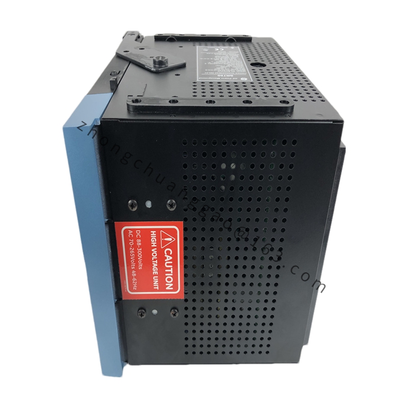
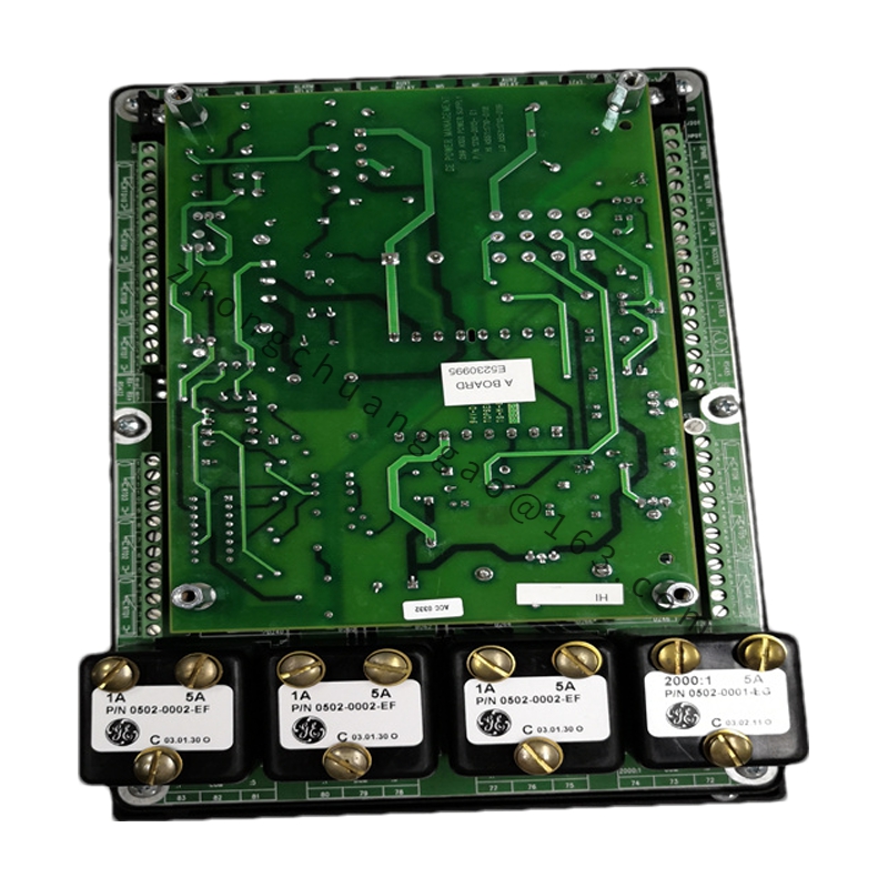
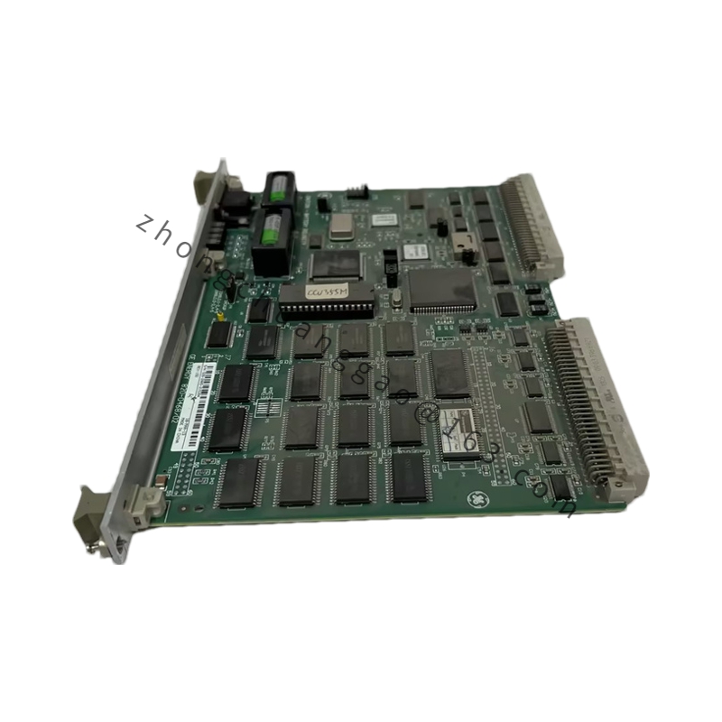
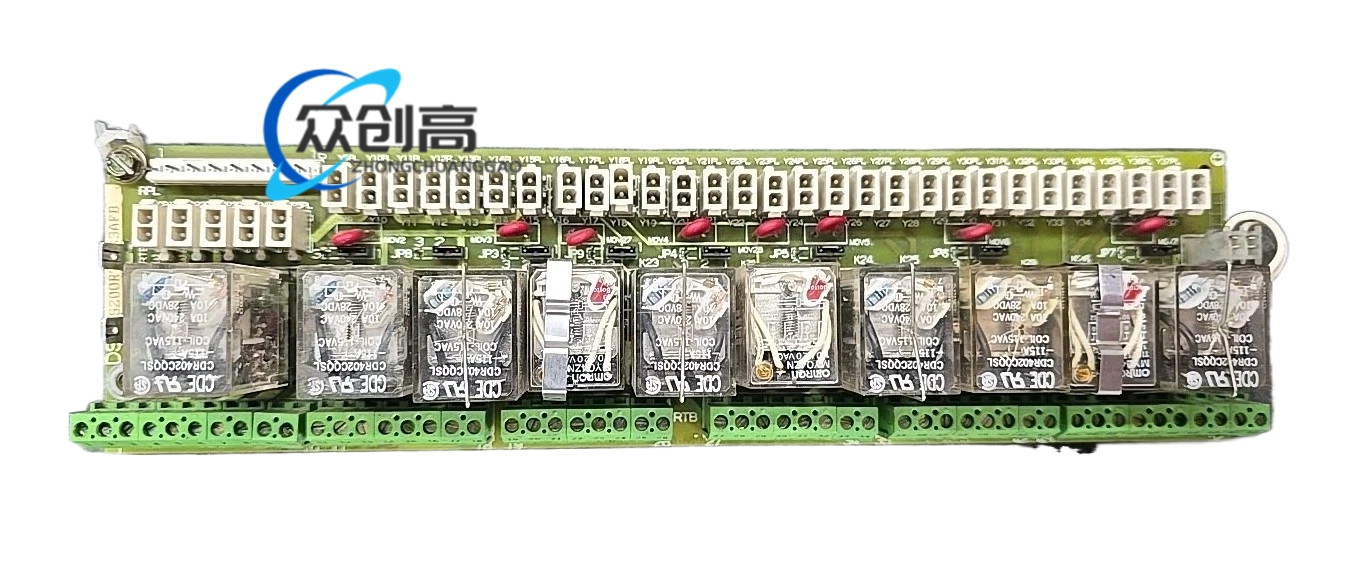
This board provides logic power and signal conditioning for turbine control and drive assemblies. It is a revised version of the original DS200SDCIG2 parent PCB, with the “AHB” suffix denoting specific functional improvements. It primarily serves as the power supply and instrumentation interface for DC2000 drives, providing multiple stabilized DC and AC voltages required by other control cards in the rack.
Detailed content

Technical Specifications
  • Manufacturer:​ General Electric (GE)
  • Series:​ Mark V (DS200 Series)
  • Functional Acronym:​ SDCI (Power Supply and Instrumentation)
  • Hardware Group:​ Group 2 (G2)
  • Power Output 1:​ +5 VDC at 4.0 A
  • Power Output 2:​ ±15 VDC at 0.4 A
  • Power Output 3:​ ±24 VDC
  • Power Output 4:​ 115 VAC at 0.4 A
  • Max Input Voltage:​ Up to 600 VAC (on compatible DC2000 drives)
  • Weight:​ Approximately 1.21 kg (2.6 lbs)
  • Fuses:​ Five onboard fuses (FU1–FU3, FU5, FU6), each with an associated LED indicator
Core Functions & Features
  • Integrated Power Management:​ Converts incoming power into multiple stabilized DC and AC voltages for other control cards
  • SCR Gating Support:​ Includes driver circuits for Armature Silicon Controlled Rectifier (SCR) gating, vital for DC motor control
  • Monitoring & Diagnostics:​ Real-time voltage and current monitoring; fuse failure LEDs
  • Interface Circuitry:​ Primary instrumentation bridge for motor field power circuits and external feedback loops
  • Configurable Jumpers:​ JP1 (MD Control Source Jumper) and JP2 (MA AC Contactor Drop-Out Time Jumper)
  • Configurable Switch (SW1):​ “Select CT Line Burdens” switch for adjusting AC line CT burdens based on nominal DC output current
Application Scenarios
Provides centralized power and instrumentation interfacing for CPU boards, SCR gate drives, and cabinet fans within Mark V control cabinets for 6B, 9E, 7FA, and H-class gas turbines. When plant voltage fluctuates within ±10%, the module maintains stable output, avoiding turbine trips due to power dips.
Installation & Maintenance Guidelines
  • ESD Sensitivity:​ Highly susceptible to electrostatic discharge. Always wear a grounded wrist strap and keep the module in its protective antistatic bag until installation.
  • Replacement:​ Disconnect all power to the drive assembly before swapping boards. Refer to GE Instruction Manual GEI-100173 for the specific replacement sequence.
  • Configuration Matching:​ Upon installation, all jumpers and the SW1 switch settings must be manually verified and adjusted to match the settings of the board being replaced.
  • Live Swapping:​ Not recommended; power down before removal.

You may also like