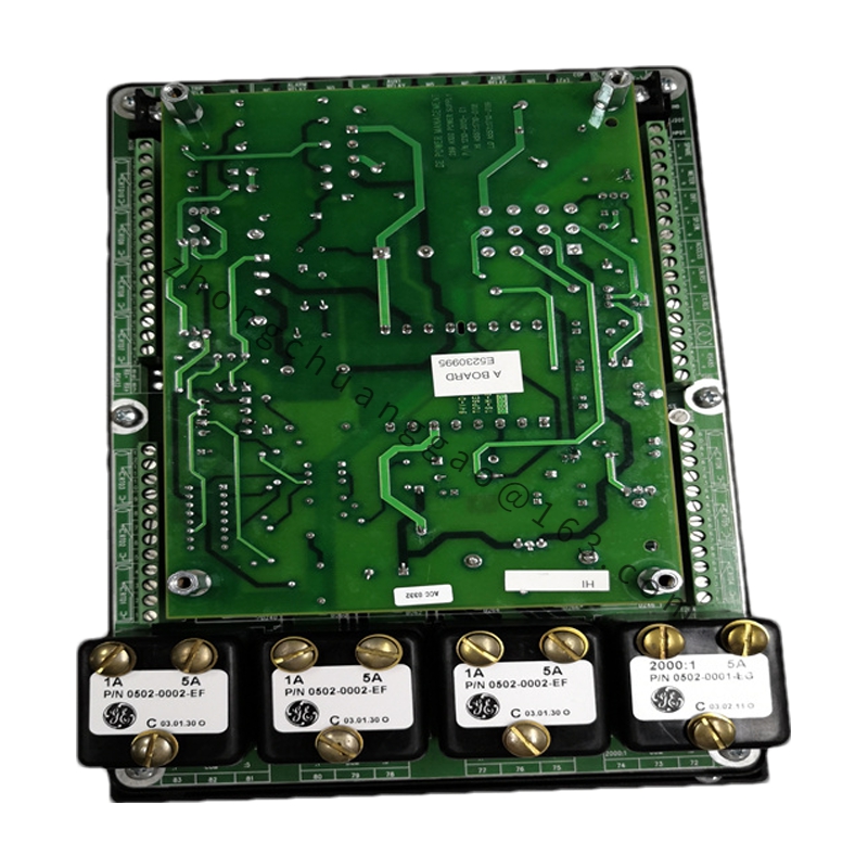
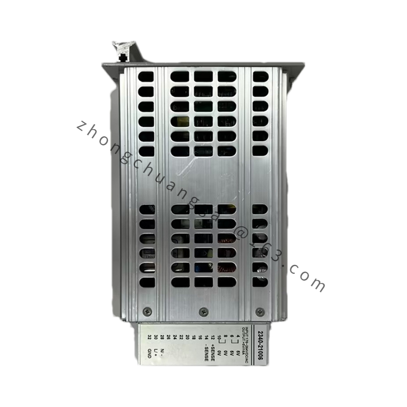
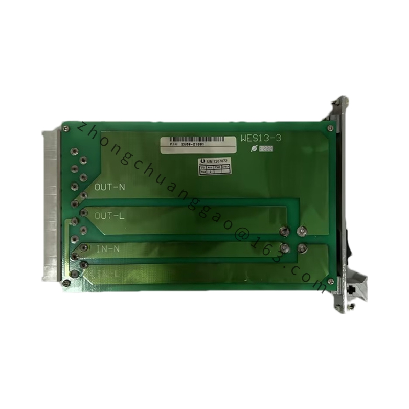
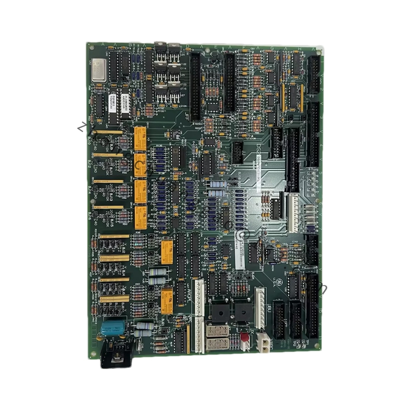
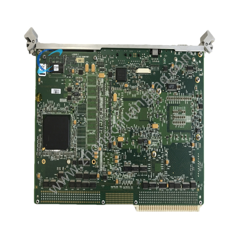
-
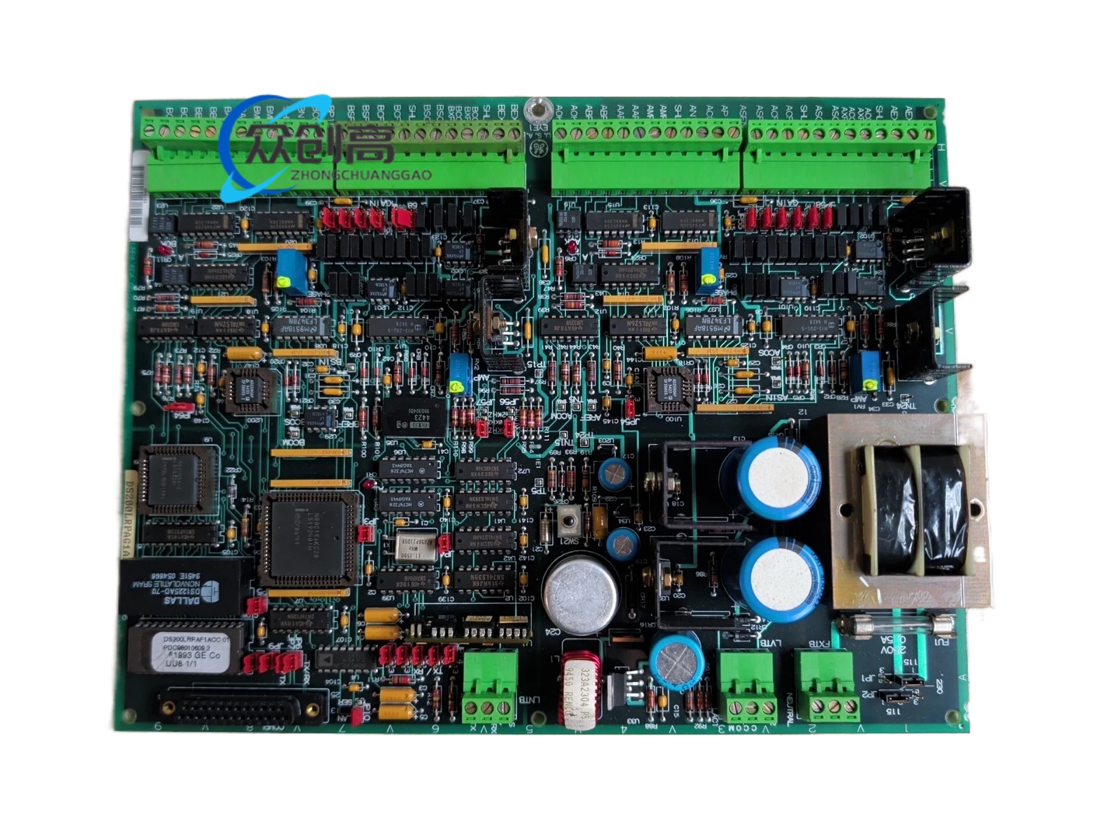
Input Voltage: Up to 600 VAC (depending on system configuration)
-
Field Output Current: 10 A internal NRX; 15 A fused output
-
Field Control Type: Non-reversing, non-plugging (NRX)
-
Snubber Circuits: AC and DC snubbers for transient protection
-
Fuse Indicators: Neon lights for blown fuse detection
-
Field Current Regulation: Thyristor-diode bridge
-
External Field Support: Compatible with external exciter modules
-
Mounting: Rack-mounted in Mark V cabinet
-
Operating Temperature: –30°C to +65°C
-
PCB Protection: Conformal coating
-
Certifications: UL, CE, RoHS
-
Included Fuses: FU1 (115 VAC power supply), FU2/FU3 (signal-level power supply), FU5/FU6 (internal NRX/MOV assembly)
-
Customizable Components: Jumpers (JP1, JP2), Switch (SW1 for AC line CT burdens)
-
Functional Revisions: 1st = A, 2nd = F; Artwork Revision B
-
Working Principle: Converts incoming AC field power (up to 600 VAC) into regulated DC outputs via a thyristor-diode bridge, providing NRX field control at 10 A internally (15 A fused), while AC and DC snubber circuits suppress voltage transients. Multiple power supplies feed motor field circuits and signal-level electronics.
-
Key Features:
-
Seamless integration with GE Speedtronic technology for precise turbine control
-
Comprehensive fuse protection across all power rails with neon blown-fuse indicators
-
Durable conformal-coated PCB for industrial reliability
-
Jumper and switch configurability for system-specific tuning
-
Applications: Gas and steam turbine control systems, DC2000 drive platforms, power generation, manufacturing, and process automation
-
Installation Requirements: Rack-mount in Mark V cabinet; ensure input voltage does not exceed 600 VAC; set JP1/JP2 and SW1 according to system configuration.
-
Usage Notes: Inspect neon fuse indicators during maintenance; blown fuse indicates fault on corresponding rail — diagnose root cause before replacement.