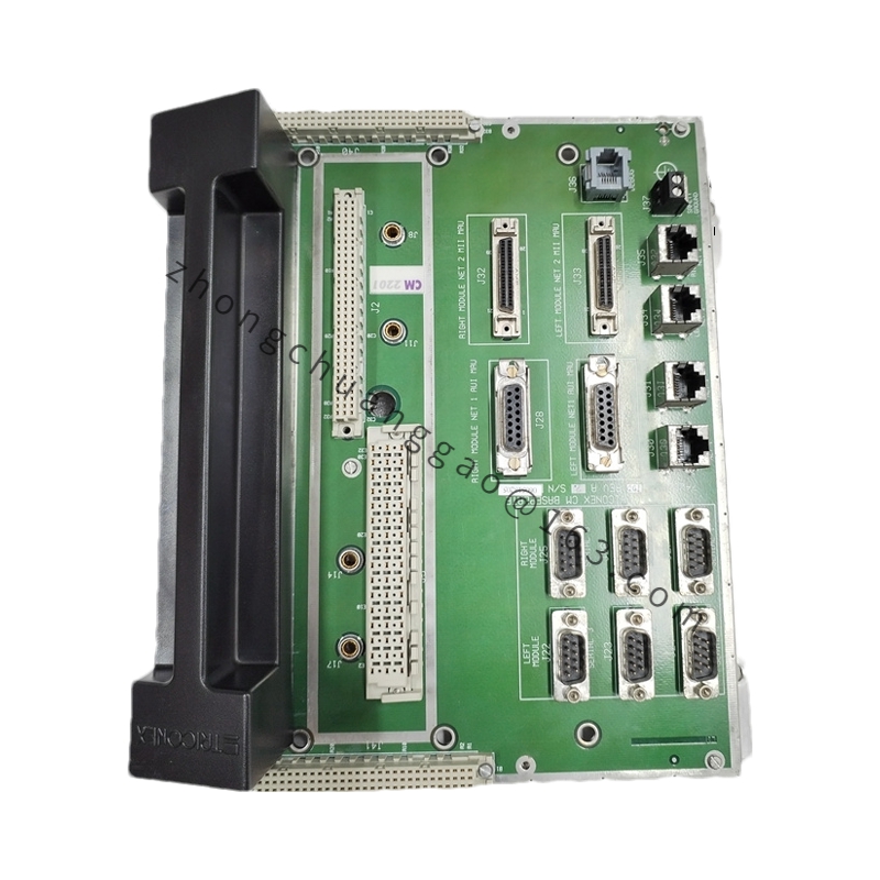
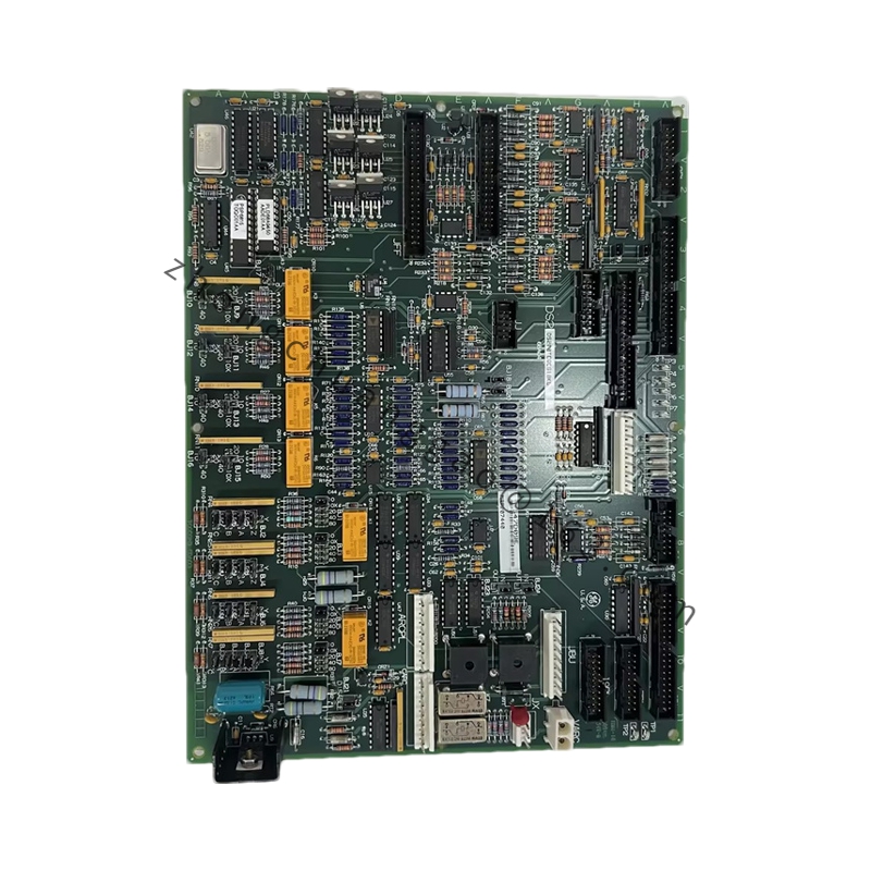
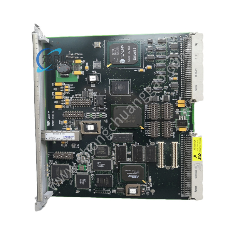
GE DS200NATOG3ACB
Product Name: Voltage Feedback Scaling Board
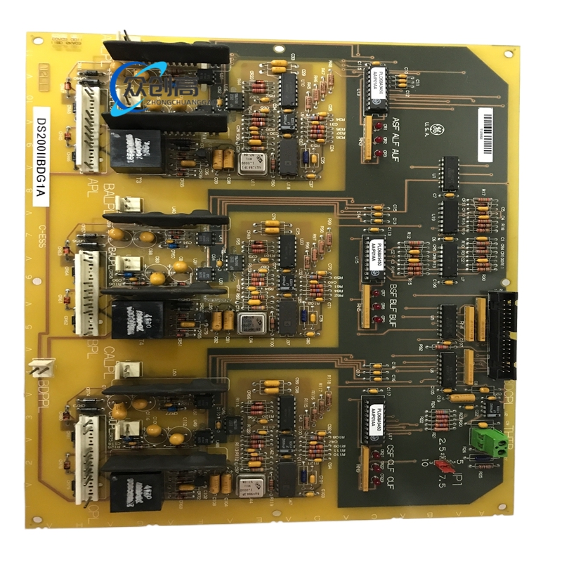
Product Overview: The DS200NATOG3ACB is a voltage feedback scaling board developed by GE for the Mark V turbine control system. Its primary function is to attenuate and scale AC and DC voltage feedback signals from the SCR bridge, allowing the control system to obtain useful voltage feedback without directly exposing low-level control electronics to the original high-voltage signal.
Detailed content
Technical Specifications:
-
Manufacturer: GE
-
Product Series: Mark V
-
Model: DS200NATOG3ACB
-
Product Type: Voltage Feedback Scaling Board
-
Board Function: Voltage feedback scaling and attenuation
-
Main Application: GE Mark V turbine control system
-
Input Configuration: Five independent resistor strings
-
Voltage Channels: Three AC phase inputs plus positive and negative DC bus inputs
-
Selectable Input Levels: 6900 V, 4200 V, 3300 V, 2200 V, 1200 V
-
Configuration Method: Input stab connectors and wire jumpers
-
Output Interface: 20-pin ribbon header
-
Protection: Metal oxide varistor (MOV) protection on the output circuits
-
Test Points: TPV/TEST and TP1–TP5
-
Main Connector: 20-pin vertical male connector
-
Resistor Network: Precision series resistor strings for voltage attenuation
-
Typical Application: SCR bridge voltage feedback and turbine control
-
System Compatibility: GE Mark V Speedtronic control system
-
Dimensions: 180 × 50 × 100 mm
-
Weight: 0.42 kg
Functional Features:
-
Scales and attenuates AC and DC voltage feedback signals
-
Handles feedback from three AC phases as well as positive and negative DC bus voltages
-
Provides configurable attenuation for five input voltage levels
-
Integrates MOV protection on output circuits
-
Plays an important role in voltage measurement, SCR bridge monitoring and related turbine control functions
Working Principle: The board uses precision resistor strings to reduce the amplitude of incoming AC and DC voltage signals from the SCR bridge. This attenuation ensures that the feedback signals can be safely processed by the control system. The five independent resistor strings are specifically arranged to handle different types of voltage inputs, with one string dedicated to each of the three AC phases and one string each for the positive and negative DC bus voltages.
Application Scenarios: SCR bridge voltage feedback and turbine control.
Configuration Notes: The appropriate voltage configuration is selected using the input stab connectors and wire jumpers provided on the board. Correct configuration is essential because the attenuation ratio determines the relationship between the actual high-voltage input and the scaled feedback signal delivered to the control system. Before changing any input configuration, the actual system voltage and the required board configuration must be verified against the equipment documentation and applicable maintenance procedures.
Installation: Installed in the corresponding Mark V control system.