Digital guide

You are here:

GE DS200KLDAG1A

Product Name:​ Mark V LED Display Card / Key LED Display Card
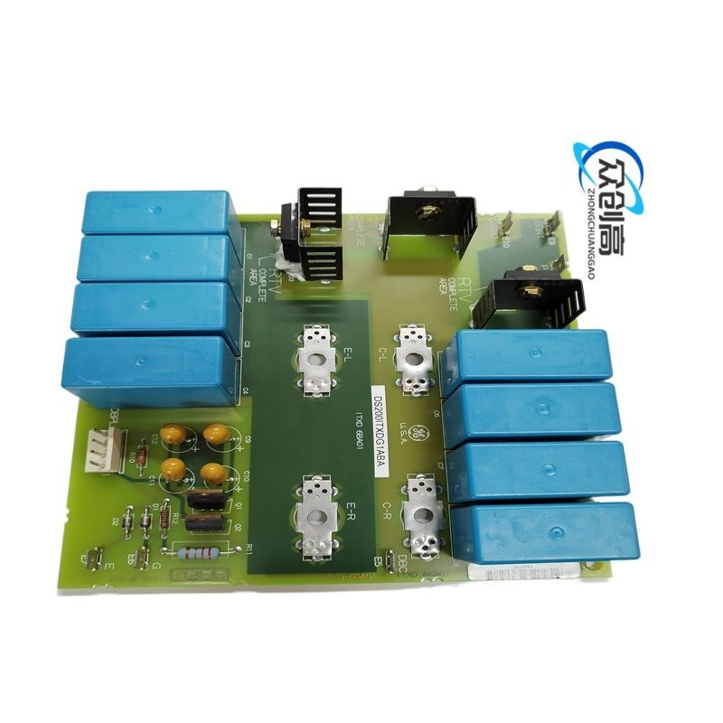
Product Introduction:​ The DS200KLDAG1A is a rectangular LED display and key interface card manufactured by General Electric for the Mark V Speedtronic turbine control system. It is deployed in steam, gas, and wind turbine automated drive and control systems to provide operators with visual status indication and local key-switch control.

Detailed content

Technical Specifications:
  • Manufacturer: General Electric
  • Series: Mark V DS200
  • Functional Abbreviation: KLDA
  • LEDs: 32 red LED indicators arranged in 4 rows of 8
  • Auxiliary Display Boards: 7 secondary boards, each with a 10-digit SISD (16-segment) LED display
  • PCB Construction: Multi-layer with EEPROMs and three FPGAs
  • Oscillator: Onboard oscillation chip
  • Mounting: Drilled and marked for alignment; brass pins connect auxiliary boards
  • Status: Discontinued (Legacy)
Functional Features:
  • Drives seven 10-digit alphanumeric LED display segments for turbine parameter readout
  • 32 discrete red LEDs provide row/column status and fault annunciation
  • Onboard EEPROM stores configuration and calibration data
  • Three FPGAs handle display multiplexing, key decoding, and communication with the Mark V controller
  • Resistor network arrays and insertion connectors support flexible signal conditioning
Material Composition:
  • PCB substrate: FR-4 glass epoxy
  • Capacitors: Electrolytic and ceramic
  • Connectors: 1 vertical pin connector + 3 right-angle connectors
  • Auxiliary board interlock: Side-by-side interlocking mechanical structure
  • LED color: Red
Structural Characteristics:
  • Rectangular board with GE logo and alignment codes (C-ESS, 6BA03)
  • Seven auxiliary display sub-boards locked side-by-side via brass pins
  • Four connectors: one vertical pin header and three right-angle headers
  • Integrated diodes, resistors, jumper switches, and transistors
Working Principle:​ The main controller sends serialized display data and key-state requests over the backplane. The onboard FPGAs demultiplex the data stream, drive the 16-segment LED displays through current drivers, and scan the key matrix. EEPROM stores character maps and board identification. The 32 red LEDs are driven directly from FPGA I/O through current-limiting resistor networks.
Installation Requirements:
  • Mount in the designated Mark V control panel slot using drilled mounting holes
  • Align auxiliary boards via brass pins; ensure side-by-side interlock is fully seated
  • Connect the vertical pin connector and three right-angle connectors to the corresponding backplane headers
  • Verify board codes (6BA03, C-ESS) match the panel drawing before power-up
Usage Precautions:
  • The DS200KLDAG1A is discontinued; verify spare board authenticity and EEPROM contents before swap
  • Avoid bending the auxiliary board interlocks during insertion
  • Confirm correct polarity of electrolytic capacitors when performing repair
  • Keep the board away from moisture and conductive dust to prevent LED segment short circuits

You may also like