GE DS200HSTIG1AAA
Product Brief:
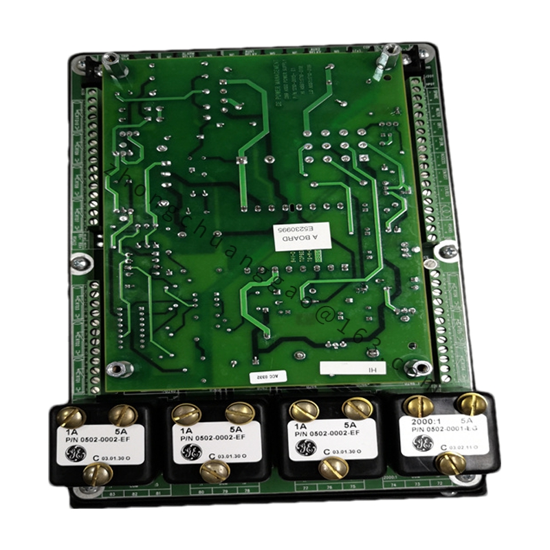
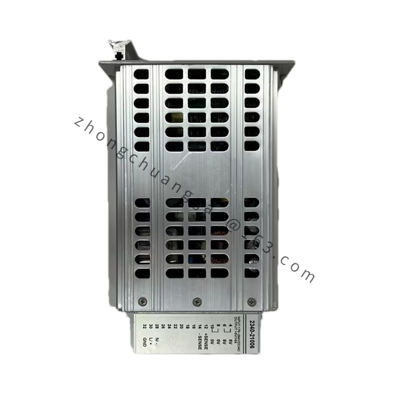
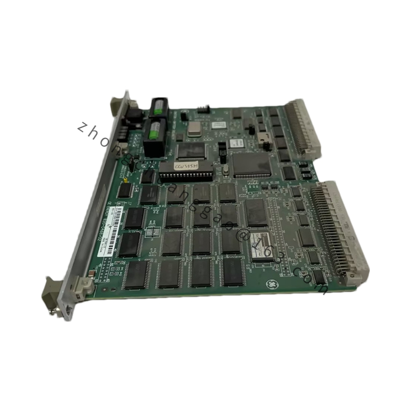
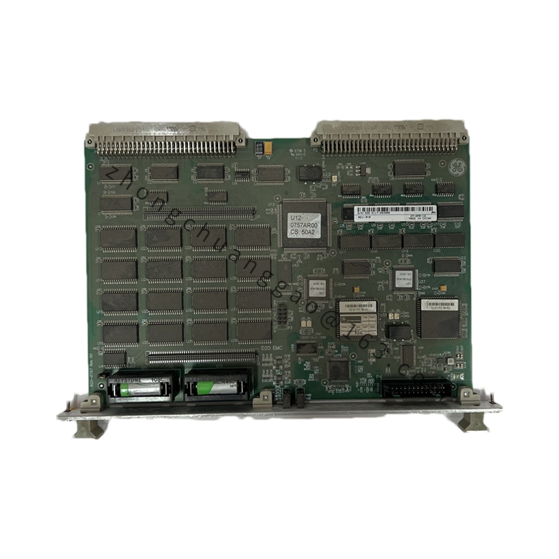
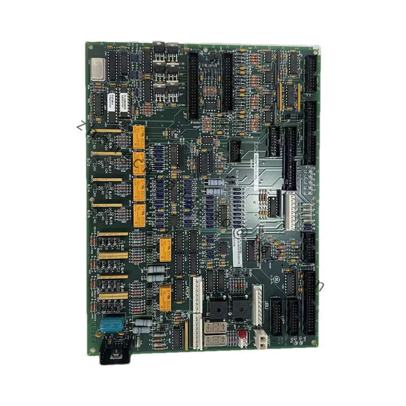
High-speed protective interface board that receives turbine speed-probe and protection-vote signals from the Mark V control core and drives immediate trip/shutdown actions for gas and steam turbines. It sits inside the Mark V I/O core and is one of the execution elements of the overspeed protection system (OSP). The board conditions critical discrete and pulse inputs, performs fast local decisioning and forwards trip state to relay driver boards and annunciators.
Detailed content
-
Technical Specifications:
-
Functional role: High-speed trip interface / protection execution
-
Compatible system: GE Mark V Speedtronic (simplex, dual or triple modular redundant)
-
Terminals: 4 screw-terminal blocks (two 3-position, two 12-position)
-
Indicators: 4 onboard LEDs for power, receive, trip-state and fault
-
Logic interface: Connects to Mark V core via dedicated ribbon/cable header (not backplane-only)
-
Signal types handled: Speed-pulse inputs, overspeed votes, protection interlocks, trip relay drive
-
Response: Real-time detection of overspeed and critical trip events; sub-cycle protective action relative to Mark V scan
-
Power: Derived from Mark V core logic supply (+5 VDC dominant, variant-dependent aux rails)
-
Construction: Industrial-grade FR-4 multilayer PCB, conformal-coated component side, gold-edge connector
-
Operating temperature: 0 °C to +60 °C (control-room enclosure class)
-
Weight: Approx. 1 kg with terminal hardware
-
-
Key Components: Integrated circuits, resistor network arrays, diodes, electrolytic and ceramic capacitors, LEDs, DIP switches/jumpers (revision dependent), terminal blocks.
-
Functional Features:
-
Direct execution path for overspeed and emergency trip, independent of main control loop latency
-
LED-based local diagnostics for installers and maintenance staff
-
Supports simplex, dual and TMR Mark V architectures
-
Isolated field terminals separate turbine-protection wiring from core logic
-
Works with VPRO/HMFP protection processors and HRRA relay driver boards
-
-
Working Principle:Speed sensors and protection logic in the Mark V core feed pulse/discrete signals to the HSTI through a controlled cable connection. The board conditions and validates those signals, applies debounce/voting rules consistent with the configured redundancy mode, and asserts a hardwired trip output to downstream relay boards when an overspeed or protected-event threshold is met. LEDs reflect live state; terminal blocks land field-side trip and monitor wires.
-
Application Scenarios:
-
Gas turbine overspeed protection and emergency shutdown
-
Steam turbine trip execution and protection voting
-
Balance-of-plant safety chains where Mark V owns the turbine trip
-
Retrofit/spare holding for legacy Frame 5/6/7/9 turbine panels
-
-
Installation Requirements:
-
Install only in de-energized Mark V I/O core
-
Use GE-specified cable and header; do not substitute generic ribbon cables
-
Torque terminal screws to GE Mark V cabinet standard
-
Separate protection-field wiring from servo/analog signal bundles
-
Confirm redundancy mode (S/D/TMR) and jumper settings against the site control narrative
-
Verify terminal block assignment from the panel wiring diagram before closing panel
-
-
Usage Precautions:
-
Board components are static-sensitive; use grounded wrist strap and anti-static mat
-
Do not force insertion; edge connector and cable header must seat squarely
-
Never bypass trip-vote inputs or bridge terminal blocks to simulate trip
-
Test trip path during every turbine outage using approved overspeed test procedure
-
Confirm firmware/board revision compatibility with the existing Mark V core before swap
-