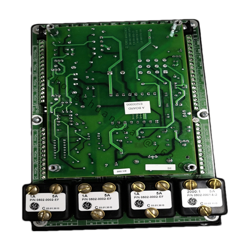
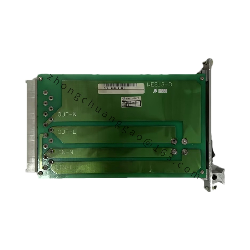
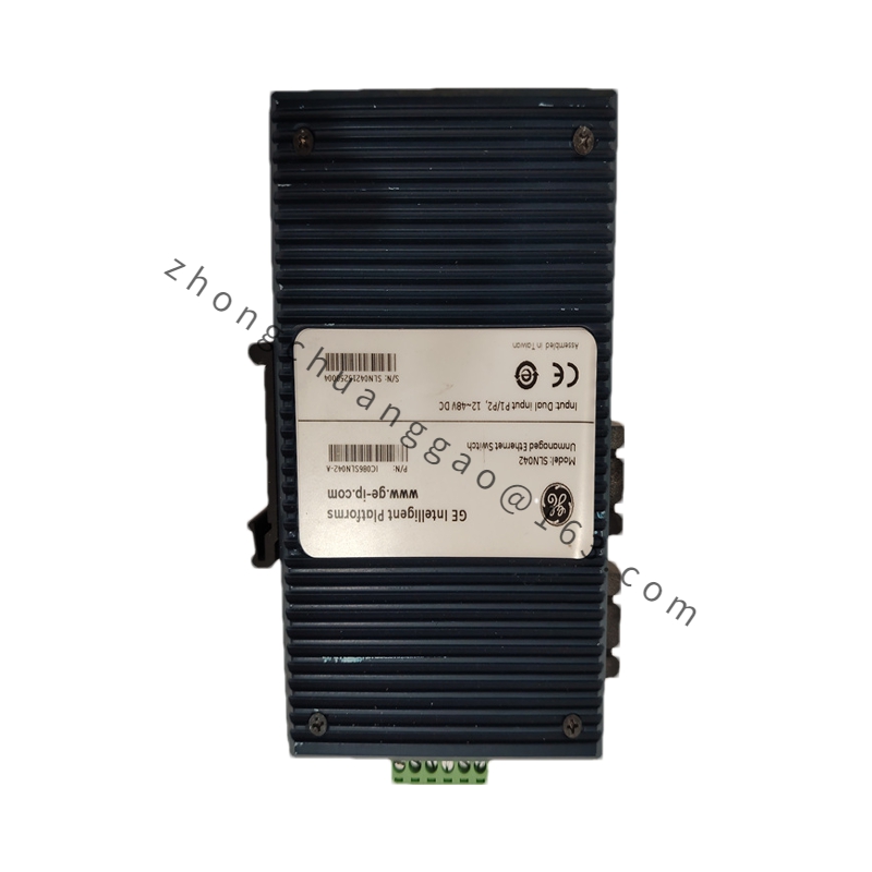
GE DS200GGIAG1B
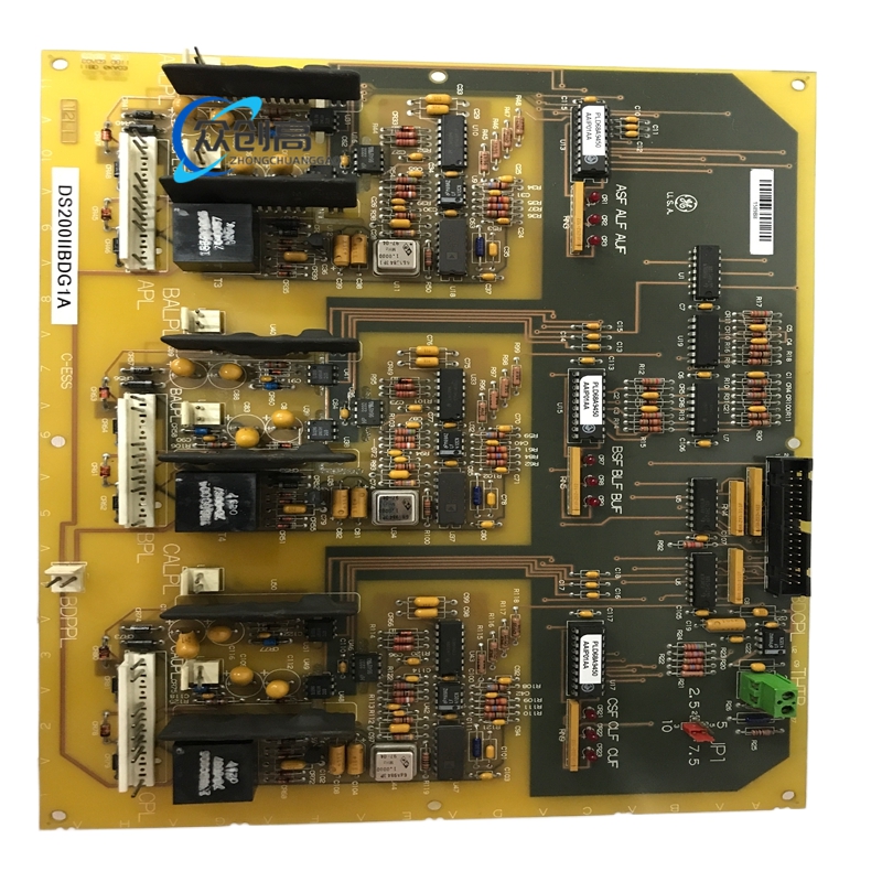
The GE DS200GGIAG1B is a GTO AC2000 Bridge Interface Board in the EX2000 series, designed for integration within GE steam and gas Speedtronic Mark V turbine control systems. It is a static-sensitive board and is stored and shipped in anti-static packaging. Detailed installation, operation, and maintenance guidance is provided in manual GEH-6120B.
Technical Specifications
- Part Number: DS200GGIAG1B
Detailed content
- Manufacturer: General Electric
- Series: EX2000
- Product Type: GTO AC2000 Bridge Interface Board
- Power Requirements: +5 VDC at 6 A
- Relay Channels: 12
- Power Supply Voltage: 28 VDC
- Mounting: DIN-rail mounting
- Technology: Surface mount
- Operating Temperature: -30°C to +65°C
- Size: 15.9 cm high × 17.8 cm wide
- Country of Origin: United States
- Manual: GEH-6120B
Component Architecture
- Two field programmable gate arrays (FPGAs)
- Over sixty integrated circuits
- Six heat sinks with mounted components
- Three relays
- Jumper switches, transistors, TP test points
- Inductor coils, various fuses, LED indicators
- Metal film resistors, capacitors, diodes
- Numerous potentiometers and over fifty resistor network arrays
- Drill holes at each corner and at the midpoint of every edge for hardware mounting with standoffs or screws (holes are insulated against surface voltage)
Functional Features
- Serves as the AC2000 bridge card providing interface between the control system and the power bridge in industrial drive applications
- 12 relay channels for control and signaling
- Surface mount technology for high-density integration
- DIN-rail mounting for flexible installation
- Wide -30°C to +65°C operating temperature range for extreme environments
Important Notes
- DS200 series boards do not contain firmware or component updates; users requiring firmware updates must use comparable DS215 boards
- The board is static-sensitive and must be handled only in static-controlled conditions
- Supported by comprehensive manual GEH-6120B for installation, operation, and maintenance guidance
Installation & Usage Notes
- Handle exclusively in electrostatic discharge (ESD) controlled conditions
- Mount via DIN rail or screw fixing through the provided insulated drill holes
- Ensure +5 VDC @ 6 A and 28 VDC supplies are stable before energizing
- Observe the -30°C to +65°C ambient operating range
- During maintenance, carefully inspect solder joints and connector seating given the extensive FPGA and relay population
- Refer to GEH-6120B manual for detailed guidance to maximize performance and ensure correct usage