GE DS200GGDAG1A
Product Name: GE DS200GGDAG1A GTO Gate Driver Board (Mark V Series)
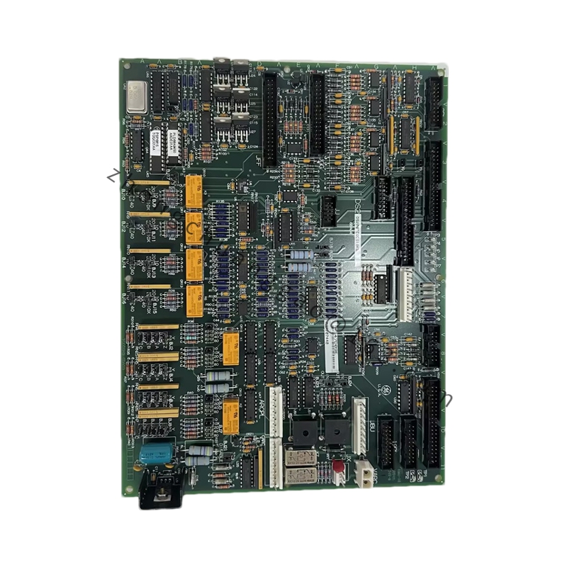
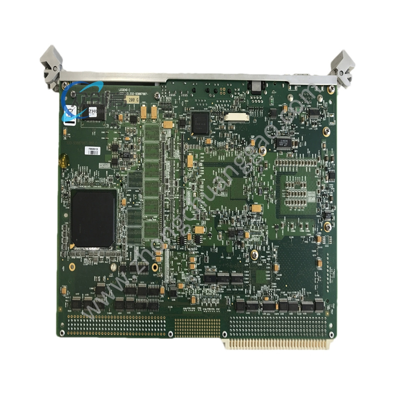
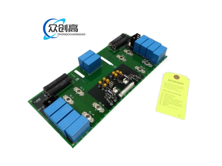
Product Overview: The DS200GGDAG1A is a GTO (Gate Turn-Off) thyristor gate driver board designed for GE’s Mark V turbine control and medium-voltage drive systems. It generates and shapes the high-current gate pulses required to turn GTO/SCR bridges on and off in EX2000/EX2100 and similar drive platforms. Typically, one card serves a six-pulse bridge, replacing six individual gate amplifiers, a high-voltage isolator, and a timing network in a single plug-in module.
Detailed content
Technical Specifications:
- Manufacturer: General Electric
- Series: Mark V DS200 / AC2000 Drive Control
- Board Type: GTO Gate-Driver Board
- Gate Output: 240 V DC, 6 A peak per channel
- Isolation: 2 kV basic gate-to-logic isolation
- Gate Timing Adjustment: 6 surface-mount trim pots for turn-on/turn-off timing balance
- Connectors: 2 × 3-pin screw terminals, 2 × bayonet (gate out), 1 × 34-pin control header
- Status LEDs: 2 groups (red, amber, 2 green) per channel for gate OK / fault indication
- Switching Frequency: Up to 500 Hz (GTO limited)
- Operating Temperature: –40°C to +70°C
- Dimensions: 159 × 178 mm
- Weight: 1 lb (0.45 kg)
- Mounting: Mark V card-file, stand-offs at corners
- PCB Coating: Normal thickness, anti-static / moisture barrier
Functional Features:
- Shapes high-current gate pulses for reliable GTO switching
- Onboard trim pots enable timing balance across all six devices within 500 ns
- 2 kV isolator keeps high-voltage bridge away from 24 V logic
- LED diagnostics for quick identification of weak or faulty gate channels
Performance Parameters:
- Peak gate current: 6 A
- Gate voltage: 240 V DC
- Channel-to-channel timing skew: adjustable to <500 ns
Material & Structural Characteristics:
- Industrial-grade PCB with anti-static and moisture barrier coating
- Corner stand-offs for secure card-file mounting
- Screw terminals and bayonet connectors for robust industrial connections
Working Principle: The board receives control signals from the drive regulator and generates precisely timed, high-current gate pulses. The 2 kV isolation barrier separates the low-voltage logic side from the high-voltage GTO bridge. Each of the six channels can be individually trimmed using surface-mount potentiometers to ensure all GTO devices switch simultaneously, preventing uneven current sharing that could destroy a device.
Installation Requirements:
- Install in Mark V card-file with corner stand-offs properly secured
- Gate leads MUST be run as twisted pair — unshielded/un-twisted leads cause dv/dt coupling into 24 V logic, resulting in random “gate fault” trips
- Ensure 34-pin control header is fully seated
- Verify gate-out bayonet connectors are locked
Usage Notes:
- Use twisted-pair wiring for all gate lead runs without exception
- Adjust trim pots only with appropriate test equipment to balance gate timing
- Monitor status LEDs regularly; amber/red indicates fault condition requiring diagnostics
- Suitable for 7FA peaker applications with typical swap time of five minutes