Product Name: Enhanced Analog Output Board (Mark V DS200 Series)
Product Introduction: The DS200FECBG1A is an enhanced 8-channel analog output board in GE’s Mark V DS200 family. It replaces the original G1 version with faster update rates, lower drift, and improved resolution, targeting fast closed-loop control applications such as pressure control in gas compressor stations where valve lag causes oscillation.
Update rate: 1 ms per channel (8 ms for all 8 channels)
Watchdog timer: Hardware-based, resets all outputs to 4 mA on backplane communication loss
Short-circuit protection: 30 mA current limit
Status LEDs: 8 green + 1 yellow (watchdog)
Power draw: +5 V @ 450 mA
Operating temperature: 0 to +50°C
Terminal block: 16 positions
Functional Features:
1 ms per-channel update (half the original G1’s 2 ms)
16-bit resolution delivering 0.25 µA per count
Faster output drivers vs. G1
Improved temperature drift from ±0.01%/°C to ±0.005%/°C
Onboard watchdog that forces outputs to 4 mA saf-state on comms loss
Additional watchdog status LED on the faceplate (distinguishes G1A from G1)
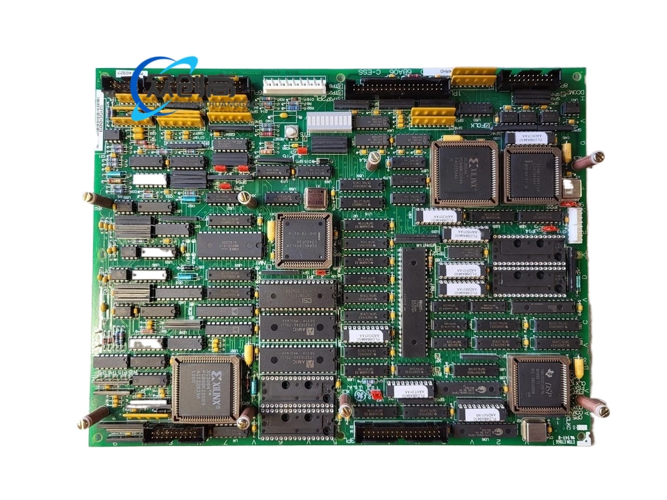
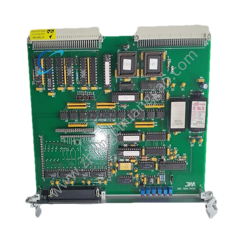
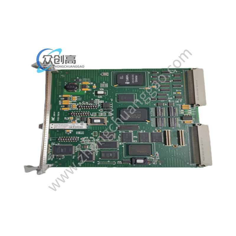
Material Composition: Industrial-grade PCB with surface-mount components, DIN connector interface, and a 16-position terminal block. The “G1A” revision carries an updated faceplate with an additional LED.
Structural Characteristics: 16-position terminal block; front-panel faceplate with 8 green channel LEDs plus 1 yellow watchdog LED; backplane interface via DS200 board edge connector.
Working Principle: The main controller sends digital output commands over the backplane. The board’s per-channel D/A converters source 4-20 mA signals to field devices. A hardware watchdog monitors backplane communication and drives all outputs to the 4 mA safe-fail position if communication ceases.
Installation Requirements: Insert into the designated DS200 board slot in the Mark V rack. Secure the 16-position terminal block wiring for 4-20 mA loops. Confirm +5 V backplane power is within tolerance.
Usage Precautions: Loop wiring must respect the 0-750 Ω load limit. The watchdog will force 4 mA on all outputs upon backplane communication interruption—verify this behavior is acceptable for the controlled process. The board draws 50 mA more than the G1 version; confirm the rack power budget accommodates this.