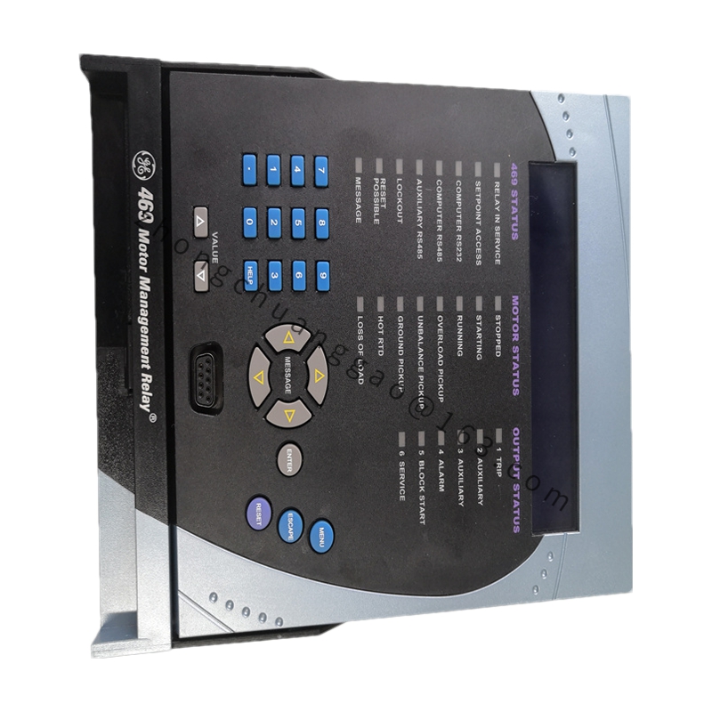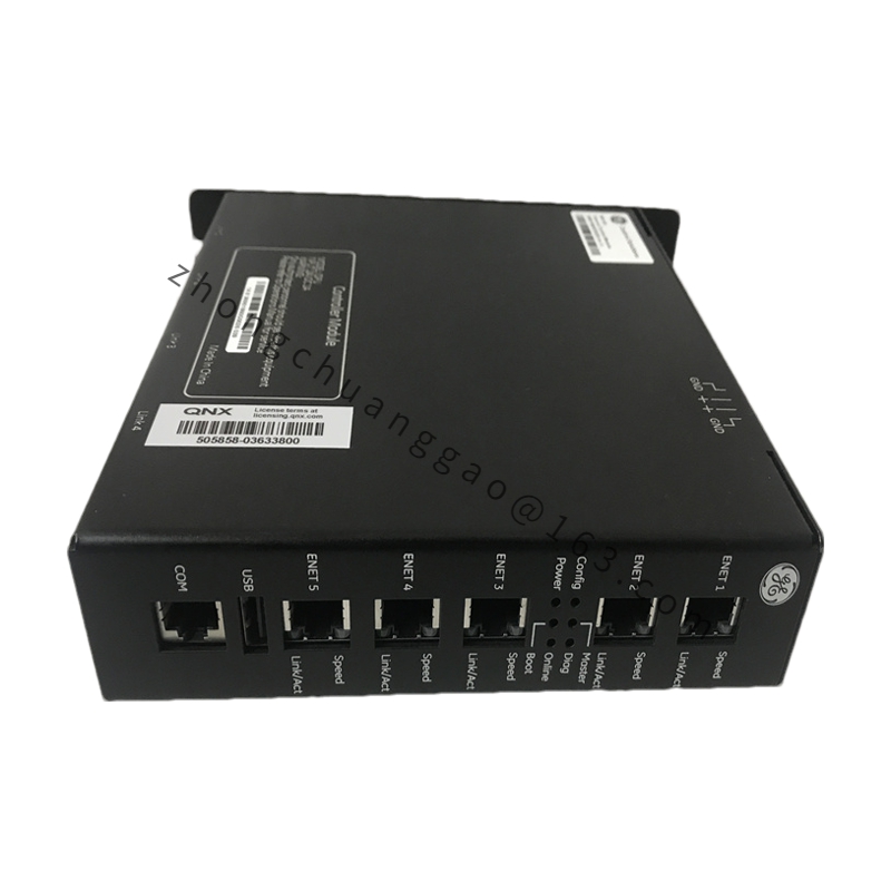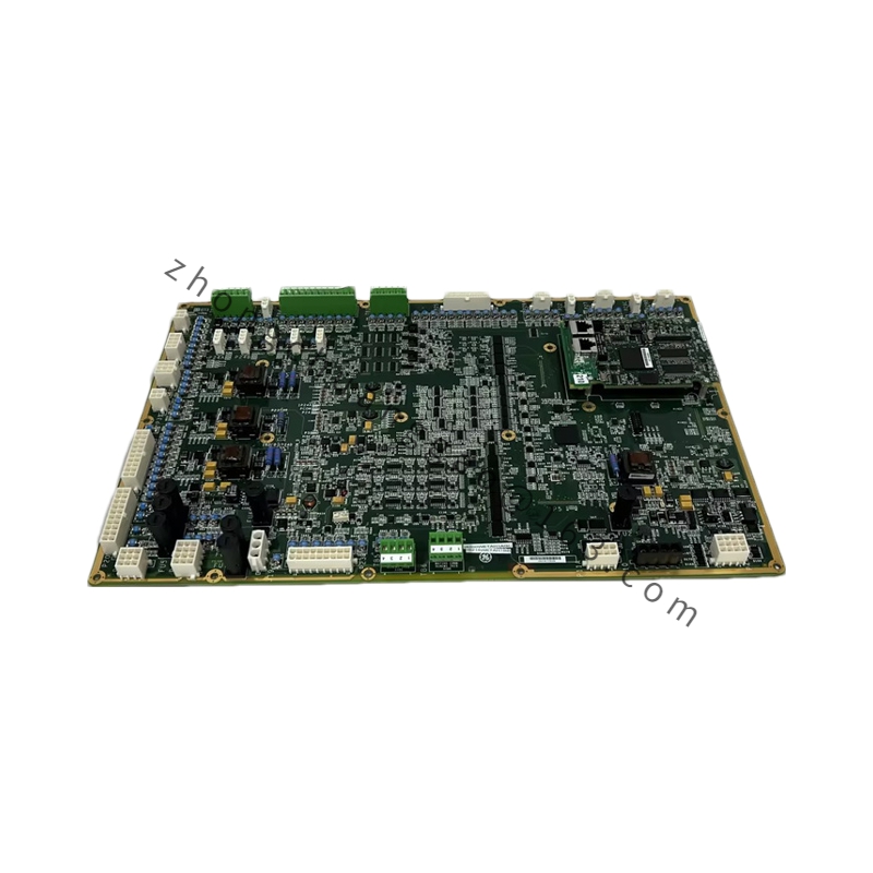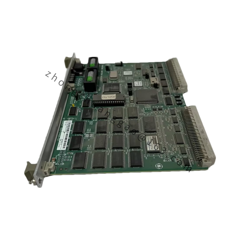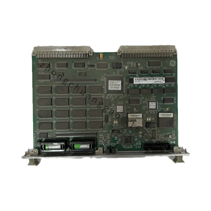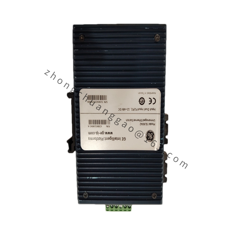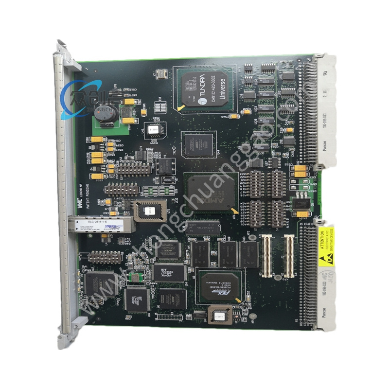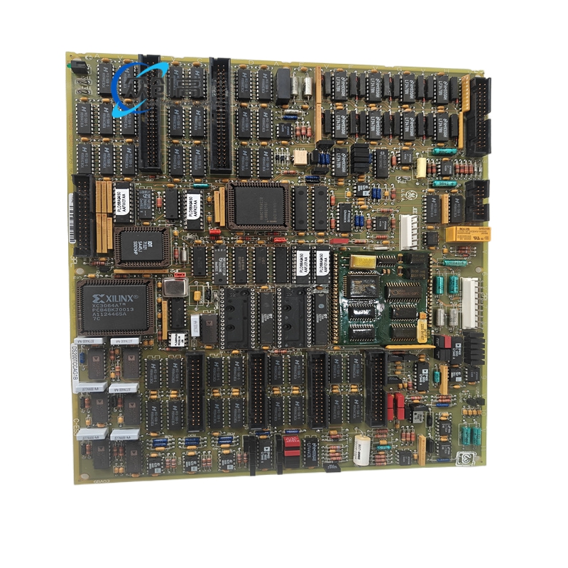
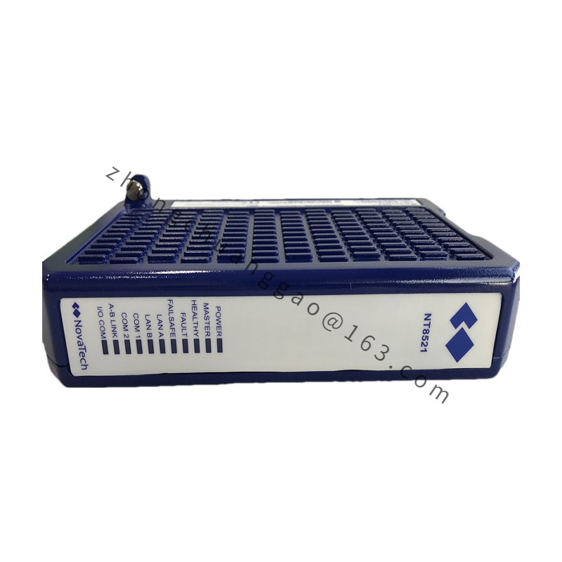
GE DS200DTBAG1AAA
Product Name: Mark V Digital Contact Input Terminal Board (DTBA)
Product Introduction: The DS200DTBAG1AAA is a digital contact input terminal board in GE’s Mark V Speedtronic turbine control system series. It serves as the passive termination layer that lands field dry-contact signals (switches, relays, interlocks) and brings them into the Mark V rack, collapsing what would otherwise be dozens of individual terminals into a single plug-in card.
Detailed content
Technical Specifications & Performance Parameters:
- Series: Mark V Speedtronic (LM — LM2500/LM6000 applications)
- Functional Acronym: DTBA (Digital Contact Input Terminal Board)
- Input Voltage Range: 24–125 VDC contact wetting voltage
- Wire Capacity: 190 wires maximum (95 per terminal block)
- Connections: J12, JQR, JQS/T, JY connectors plus two 2-pin test plugs
- Jumpers: 5 Berg jumpers (BJ1–BJ5) for input filtering / pull-up selection and test isolation
- Transient Protection: 23 metal-oxide varistors (20 mm) for transient clamping (on LM variant)
- Diagnostics Port: 9-pin D-shell RS-232 (TIMN) for laptop access
- Isolation: 500 V channel-to-ground (basic)
- Scan Rate: 10–40 ms (configurable via jumper)
- Operating Temperature: –40 °C to +70 °C (board spec); –28 °C to +55 °C (system rating)
- Dimensions: 6.25 × 5 in (159 × 127 mm) [alternate doc: 159 × 108 × 25 mm]
- Weight: 1 lb (0.45 kg) [0.36–0.8 kg depending on coat & hardware]
- Mounting: Rack mount (Mark V card-file) or panel stand-offs
- Protection Degree: IP30 front when door closed
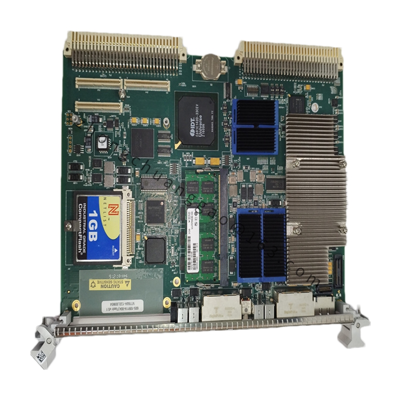
Functional Characteristics: Internally the board is a passive termination array — each input hits a pull-down resistor, a series resistor, and a varistor to ground. The Berg jumpers define the voltage window (factory default 24 V; move to 125 V pads for 110 VDC systems) and enable pull-ups or filters. The board collapses a 3-row terminal block, pull-up resistors, and noise filters into one plug-in card.
Application Scenarios: Field contact termination for Mark V turbine control systems — oil-pressure switches, temperature stats, limit switches, fire-gas switches, torque-limit relays, compartment fan interlocks on LM2500/LM6000 packages and 7EA peaking turbine panels.
Working Principle: Dry-contact field signals land on the screw terminals, pass through pull-down/series resistance and varistor clamping, and are routed via the J-connectors to the SDCC (or DSP) board in the Mark V rack, presenting clean on/off states to the controller.
Installation Requirements:
- Use a screwdriver carefully to loosen terminal screws; guide the tool with one hand to avoid damaging nearby components.
- Hold the board firmly by the sides with two hands during insertion; align mounting holes with the rack before securing.
- Always wear an ESD wrist strap connected to a grounded, unpainted metal surface.
- Apply 0.8 N·m torque to terminal screws — over-tightening cracks the posts, under-tightening allows vibration to walk wires out.
- Match the Berg jumper map in GEI-100161 before inserting the card; photograph the old board before pulling.
Usage Notes:
- Install Berg jumpers on the component side as indicated by silk-screen; installing on the reverse side causes floating inputs and false “contact open” faults.
- Meter each input pin to chassis with an ohmmeter before power-up — a blown varistor reads < 10 Ω to ground and will drag down the 24 V rail.
- The TIMN RS-232 port is 5 V referenced; plugging a grounded laptop into the 9-pin connector without an isolated USB-RS-232 dongle can short +5 V to frame ground and damage the MAX232 on the SDCC.
- Dress wires flat and lace them to the card stand-offs; 190 wires in a 4- to 6-inch slot is tight, and pigtails touching the cabinet wall cause intermittent ground faults.