Digital guide

You are here:

GE DS200DTBAG1A

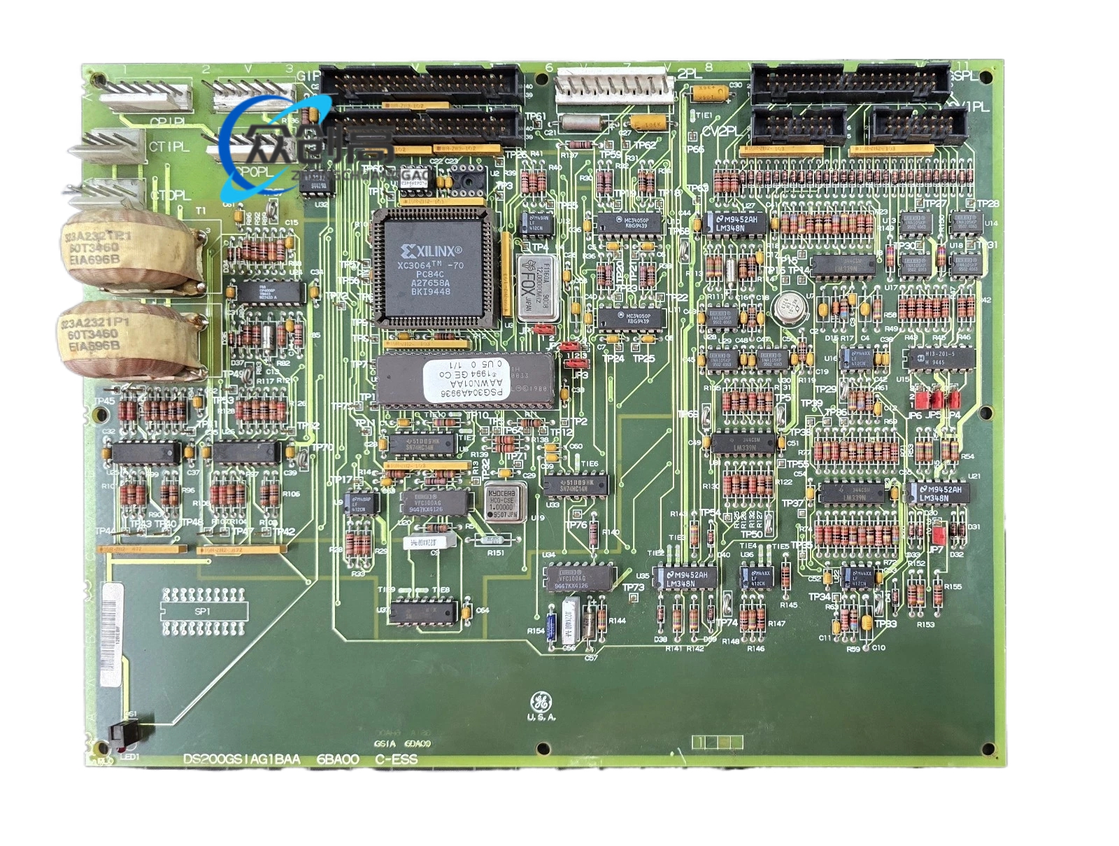
Product Name:​ 190-Wire Digital Contact Terminal Board (DTBA)
Product Introduction:​ The DS200DTBAG1A is a Mark V Speedtronic turbine control system component that provides field contact termination for discrete signals, serving as a high-density interface between field devices (switches, relays, sensors) and the Mark V control rack.
Detailed content

Technical Specifications:
  • Series:​ GE Mark V Speedtronic
  • Terminal Capacity:​ Two 95-point pluggable terminal blocks (190 contacts total)
  • Input Signal Types:​ Dry contact, 24 VDC active, or 48 VDC active (jumper-selectable)
  • Input Voltage Range:​ 24–125 VDC contact wetting
  • Output Capability:​ Relay contacts 2 A / 240 VAC (Form-A or Form-C selectable)
  • Response Time:​ ≤ 0.5 ms on, ≤ 0.25 ms off
  • Jumpers:​ 5 Berg jumpers (JP1–JP5) for pull-up and filtering selection
  • Connectors:​ 3 × 50-pin ribbon cables (JFF, JFG, JFH); 2 × 2-pin bayonet connectors
  • Isolation:​ 500 V channel-to-ground (basic); group isolation, no channel-to-channel isolation
  • Operating Temperature:​ –40 °C to +70 °C (industrial version); up to +85 °C (extended version)
  • Dimensions:​ 159 × 127 mm (6.25 × 5 in)
  • Weight:​ 0.45 kg (1 lb)
  • Protection:​ IP30 front when door closed
  • PCB Coating:​ Normal thickness with anti-static / moisture barrier
Functional Features:
  • Consolidates three DIN-rail terminal strips, pull-up resistors, and noise filters into a single plug-in card
  • Onboard RC noise filter (~1 ms) and 500 V opto-coupler per input line
  • Supports TMR (Triple Modular Redundancy) or dual-redundant architectures
  • Meets API 670 SIL2 for rotating machinery protection
Application Scenarios:​ Gas and steam turbine control cabinets (typically 7EA or 9E classes), where dozens of aux contacts (oil pressure switches, temperature stats, limit switches) must be terminated into a Mark V rack.
Installation Requirements:
  • Install jumpers JP1–JP5 per GEI-100161 jumper map before wiring — reversed jumpers cause floating inputs and false “open” alarms
  • Use a calibrated screwdriver; terminal torque is 0.8 N·m (over-tightening cracks screw posts, under-tightening allows vibration loosening)
  • Route the 190-wire harness flat against card stand-offs; leaving the bundle proud will cause the cabinet door to pinch conductors and create ground faults
  • Keep the cabinet door closed during operation — IP30 rating means the front is open to wash-down, salt mist, and corrosive atmospheres
Usage Precautions:
  • Verify zero voltage on all field wiring before servicing
  • Match jumper configuration to the 24 VDC, 48 VDC, or dry-contact sensing mode defined in engineering drawings
  • Ensure ribbon cable locking latches are fully engaged to resist vibration

You may also like