Product Name: DC Feedback and Power Supply Board for Mark V Speedtronic
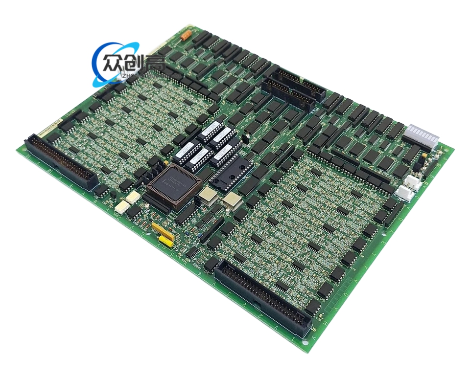
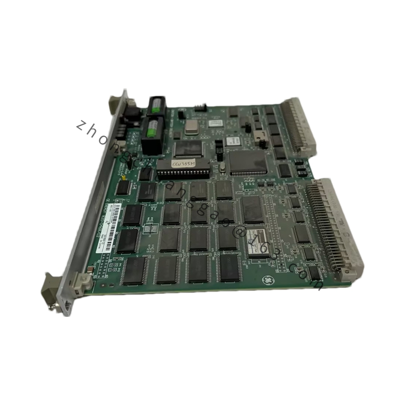
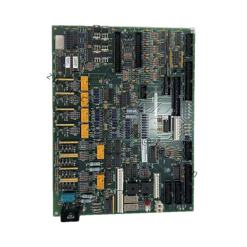
Product Introduction: The DS200DCFBG2BNC is a DC feedback and power supply board developed by General Electric for the Mark V Speedtronic gas and steam turbine control system. It supplies regulated DC power to the control rack and handles critical input/output signal routing for closed-loop turbine control.
Power Supply: +5 V DC from backplane, regulated DC outputs for control circuit supply
Operating Temperature: -25°C to +70°C
Functional Features: The board carries three distinct hardware revisions (B, N, C) that alter performance specs from the original DS200DCFBG2 parent board. The 3-fuse protection circuit prevents cascading electrical faults. The 7 DIP switches allow selection of AC line voltage and tuning of DC bridge feedback.
Application Scenarios: Gas turbine power generation, steam turbine management, and legacy plant maintenance for discontinued Mark V systems. The board’s 9 stab connectors ensure stable signal transfer, preventing erratic turbine behavior during peak load.
Working Principle: Within the Mark V Speedtronic system, the DS200DCFBG2BNC sends and receives critical input/output signals while maintaining stable DC output. The transformers and resistor networks handle signal conditioning, while the fuses and indicators provide visual fault detection.
Installation Requirements: Verify the exact B/N/C revision requirements before installation. Ensure proper seating of the 18 plug and 9 stab connectors.
Usage Precautions: When the neon/LED indicators are lit, the power supply fuse is blown—check the 3 dedicated fuses immediately and replace with identical rating. For turbine speed/power fluctuations, inspect connectors for seating issues or oxidation. Use the 5 TP test points to verify voltage signals if no DC output is present.