Digital guide

You are here:

GE DS200CTBAG1ADD

Product Name
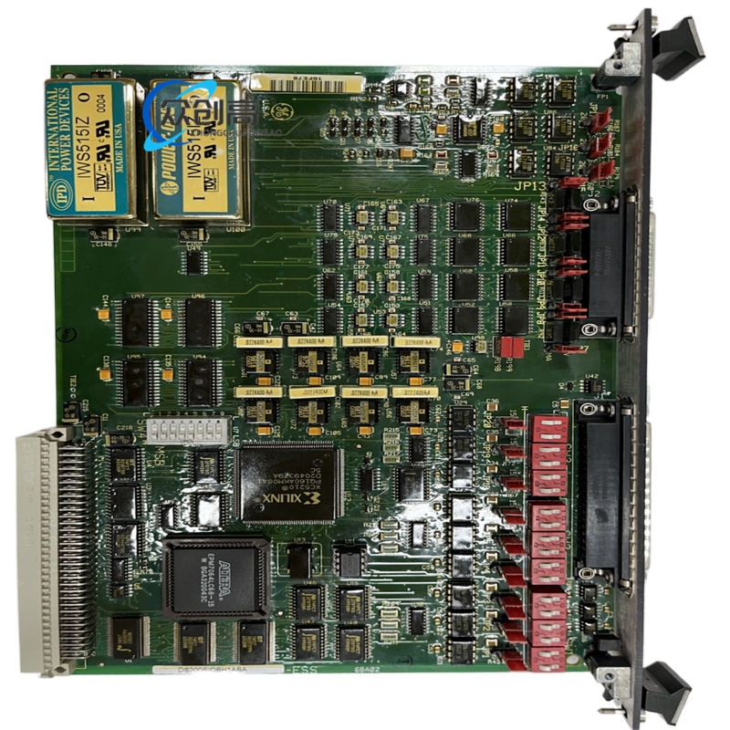
GE DS200CTBAG1ADD Control Terminal Board (CTBA)
Product Introduction
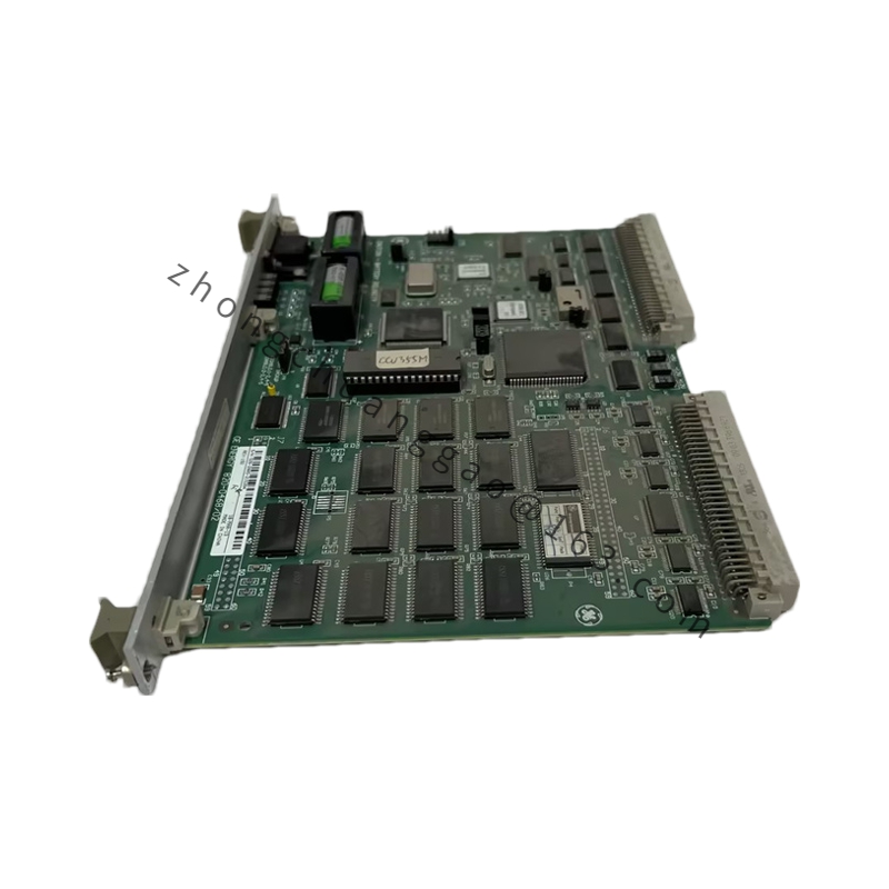
The GE DS200CTBAG1ADD is a high-density signal termination and routing board belonging to the Mark V Speedtronic control family. It bridges controller backplane logic with field wiring for analog, digital, relay, and communication circuits in turbine control cabinets.

Detailed content

Technical Specifications
  • Operating Temperature: -40 °C to +85 °C (no derating)
  • Storage Temperature: -55 °C to +90 °C
  • Humidity: 5 % to 95 % non-condensing
  • I/O Capacity: 32 mixed points (analog + digital configurable)
  • Supported Signals: 4–20 mA, 0–10 VDC, 24 VDC discrete, relay dry contact
  • Isolation: 1500 Vrms channel-to-channel and channel-to-ground
  • Power Input: 24 VDC (18–30 V range) from DS200TCPD supply
  • Dimensions: 330 mm × 100 mm × 200 mm
  • Mass: 2.0 kg
Functional Features
  • Terminates COREBUS, IONET, ARCNET, and STCA/TCDA signal paths
  • Integrates bypass relay to hold COREBUS communication during 24 VDC loss
  • Over 20 metal-oxide varistors (MOVs) and red suppression diodes
  • Twelve jumper switches for address and function reconfiguration
Material Composition
  • FR-4 laminate base with polyurethane conformal coating (humiseal class)
  • Tin/lead or lead-free soldered terminals
  • Phosphor-bronze spring and screw clamp contacts
  • Glass-reinforced nylon terminal carriers
Structural Characteristics
  • Long narrow PCB format with edge drill holes
  • Two double-deck terminal strips (up to 95 wires per strip)
  • Five vertical pin cable headers, two vertical pin sockets, one 9-pin male RS-232
  • Two COREBUS connectors (JAI/JAJ), 8PL STCA header, JAA TCCA header
Working Principle
Controller-side parallel data arrives via COREBUS/IONET headers, is conditioned by onboard resistors and varistors, and is presented to field technicians as screw-terminal points; reverse path returns field device status to the UCIB motherboard.
Application Scenarios
  • Gas and steam turbine auxiliary panel wiring
  • Compressor station control cabinets
  • Offshore FPSO machinery control rooms
  • Retrofit of Mark V Simplex/TMR I/O nests
Installation Requirements
  • Secure with M4 screws or DIN bracket to panel sub-frame
  • Torque terminal screws to 5–7 in-lb
  • Shield analog cables and ground at single point on cabinet bus
Usage Precautions
  • Unused COREBUS headers must carry termination resistors
  • Never apply 120 VAC to 24 VDC terminal rows
  • Inspect MOV discoloration during thermal inspection rounds

You may also like