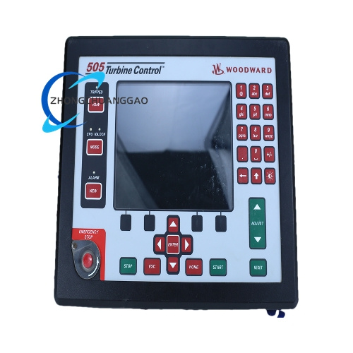
Technical Specifications
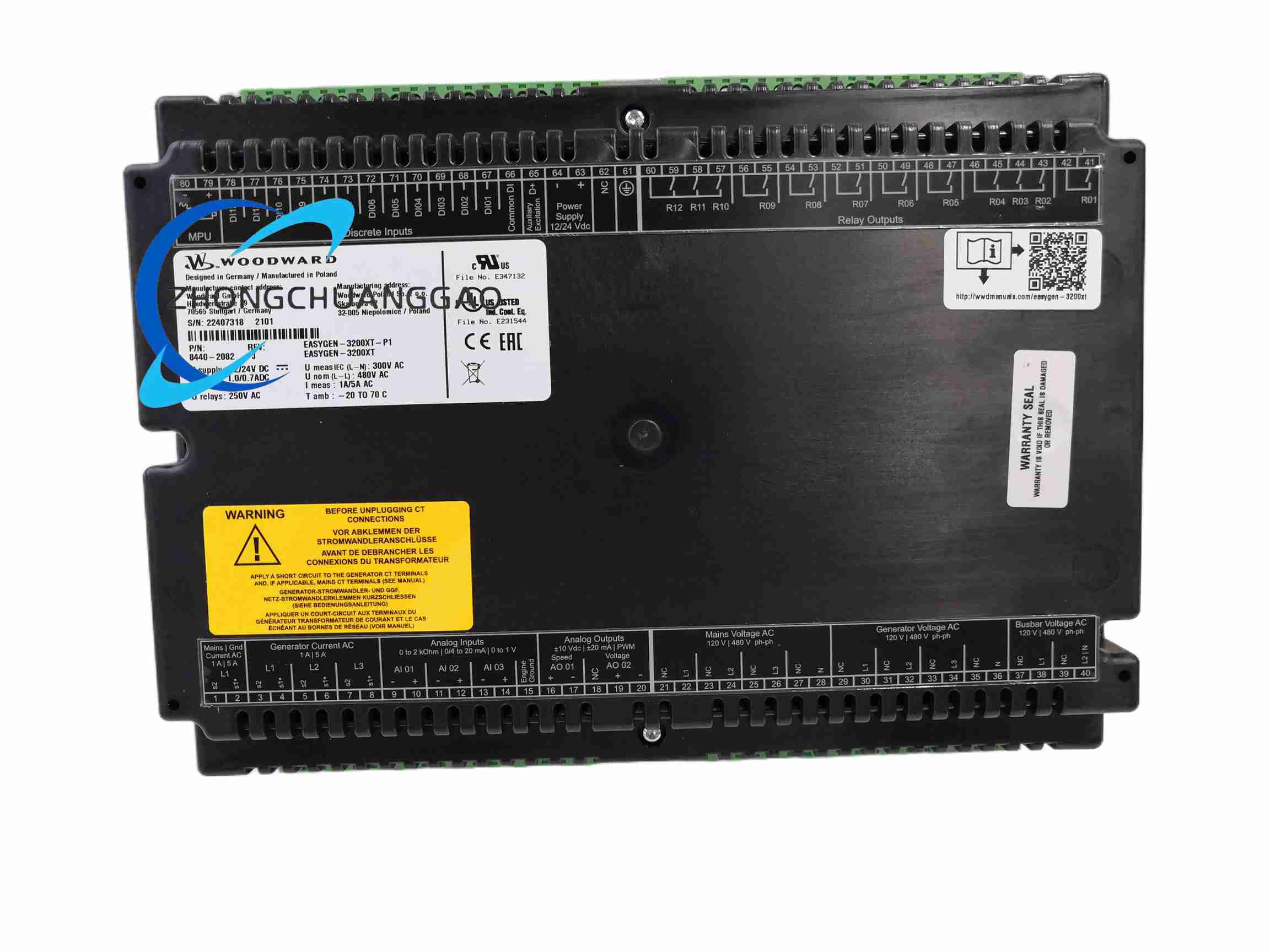
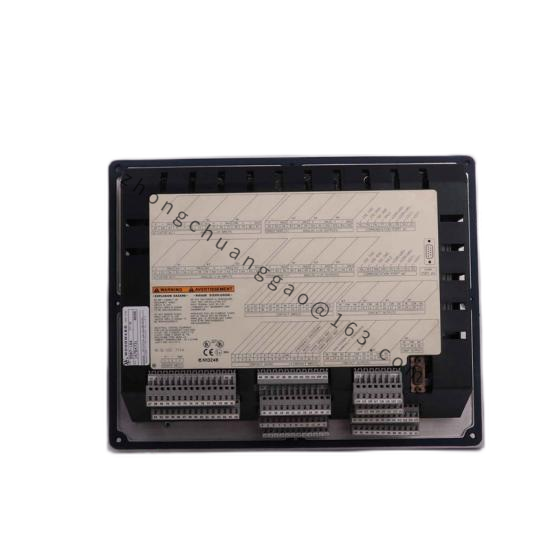
Control supply: 12/24 VDC, 8-40 VDC
Power consumption: up to 19 W
Measurement: 40-85 Hz, up to 600 VAC, 5 A CT input
Digital inputs: 14
Relay outputs: 12
Analog inputs: 3
Analog outputs: 2
Speed input: magnetic pickup
Communication: CAN 2.0B x2, RS485 Modbus RTU, RS232
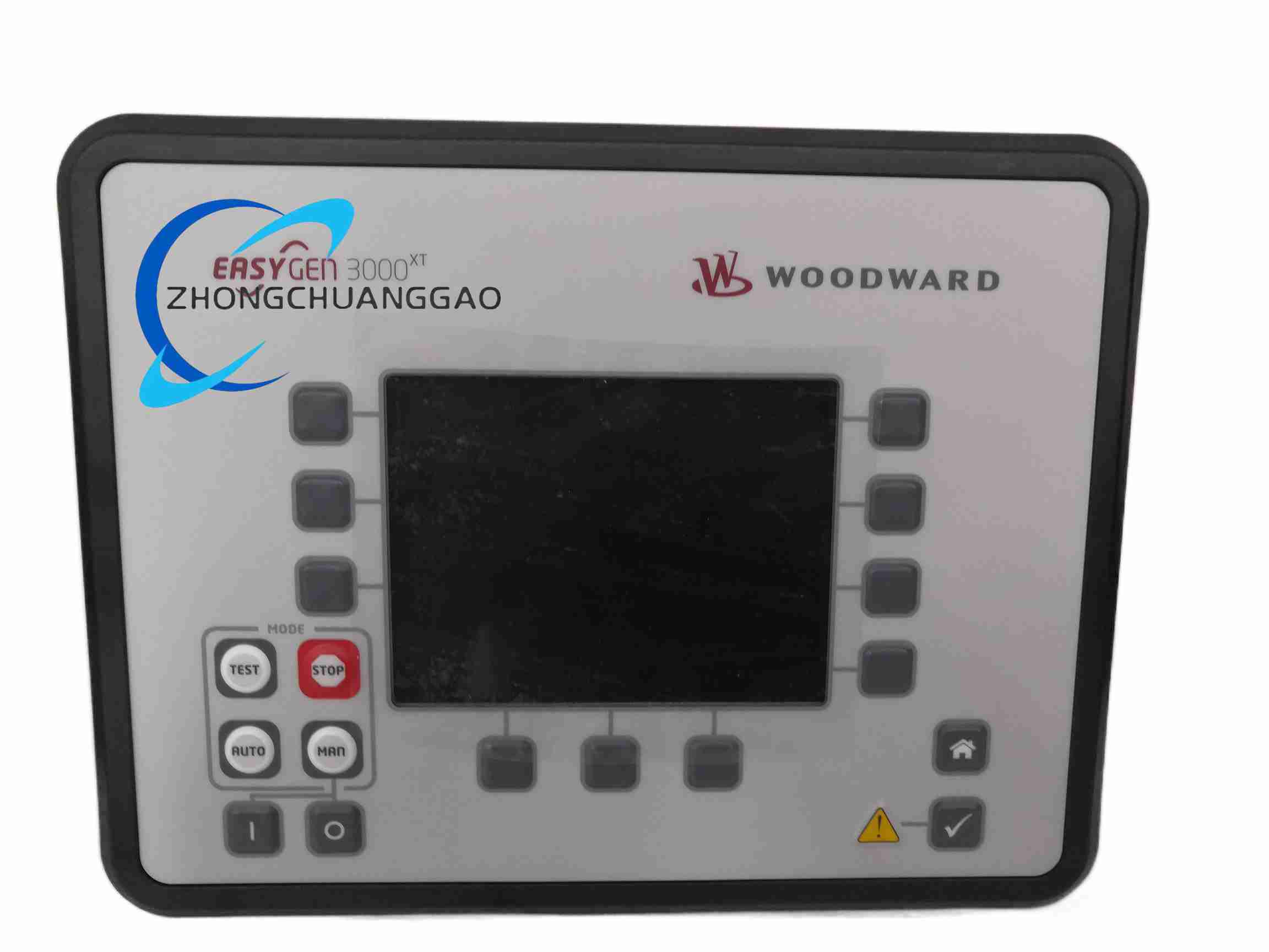
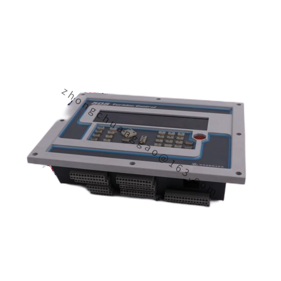
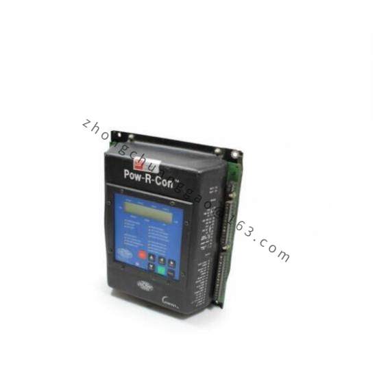
Display: 5.7-inch color LCD
Languages: 14
Front dimensions: 282 x 217 x 99 mm
Weight: approx. 1850 g
Protection: IP66 screw mount, IP54 clip mount, IP20 rear
Functional Features
Automatic start/stop and synchronizing
Load share and kW/kVAR control
AMF transfer logic
Event recording and trend view
Password-protected configuration
Application Scenarios
Diesel and gas generator sets
Standby power systems
Cogeneration and CHP
Multi-unit parallel operation
Grid-tied peak shaving
Working Principle
Measures generator and mains electrical values, controls engine governor and AVR interface, executes protection logic, and manages breaker closing or load transfer through programmable I/O and communication buses.
Installation Requirements
Flush panel mounting
Correct CT/PT wiring and polarity
Dedicated control supply
Proper grounding of communication shields
Usage Notes
P1 version does not support external CANopen I/O expansion like P2.
Do not mix mains and generator wiring incorrectly.
Configure protection thresholds before commissioning.