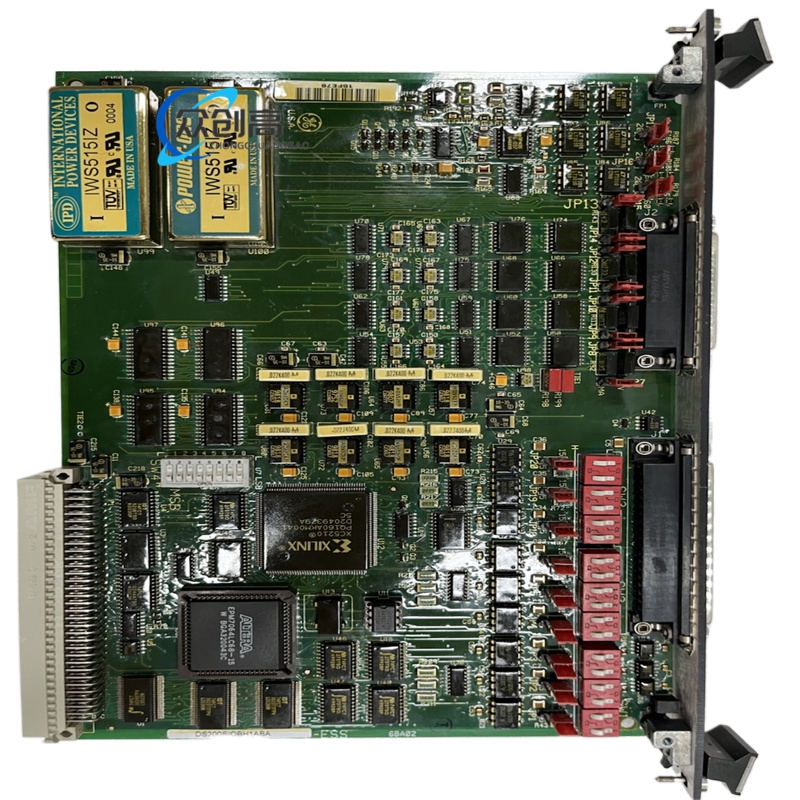
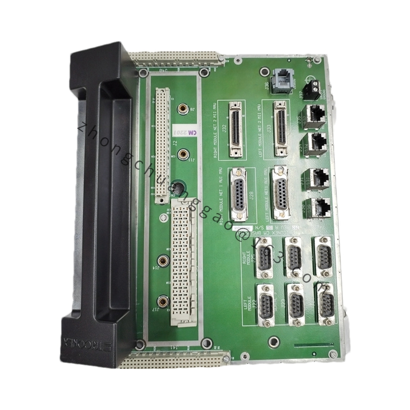
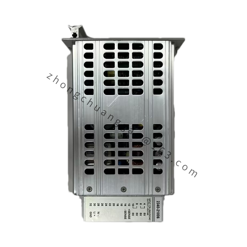
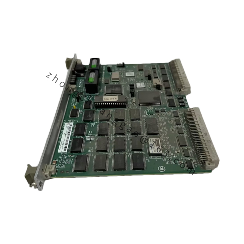
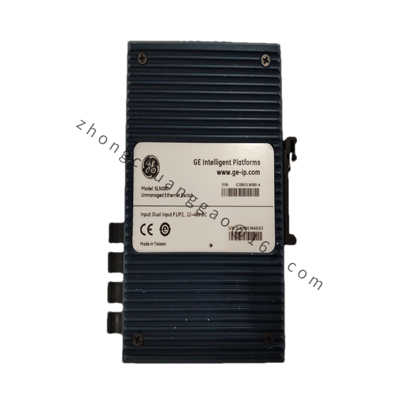
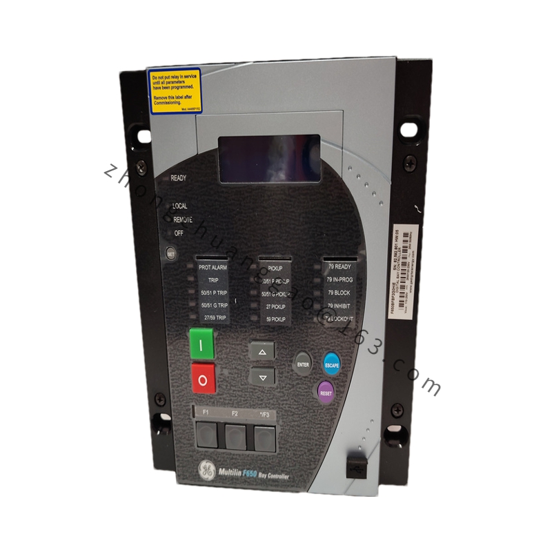
Product Name: Mark V Contactor Pilot / Test Board (CPCA)
Product Introduction: A contactor pilot board designed by GE for its Speedtronic Mark V gas and steam turbine control systems. It receives low-level logic control signals from the main controller and amplifies them into high-current drive signals to actuate power contactors, electromagnetic relays, and intermediate control circuits.
Functional Features: Built-in surge suppression, reverse-voltage absorption, and signal filtering circuits to block inductive-load transients. Provides “pull-in – hold – release” three-stage control of contactor coils. Eliminates the need for intermediate relays, reducing cabinet component count.
Application Scenarios: Contactor and relay driving in Mark V Speedtronic turbine control cabinets, EX2000 and DC2000 drive cabinets—specifically for 47/48 coil actuation, field breaker switching, and excitation contactor control.
Working Principle: The board receives a low-voltage logic command from the main controller, shapes and amplifies the signal through MOSFET drivers, and delivers a 24 V DC, 2 A peak pulse to energize the contactor coil. Dry-contact auxiliary feedback confirms the actual contactor state back to the controller.
Installation Requirements: Prior to installation, replacement, or maintenance, completely disconnect all power to the Mark V cabinet and associated control circuits. Operators must wear a grounded anti-static wrist strap (ESD protection) throughout the procedure. Align the board with the guide rails of the designated Mark V rack slot, press firmly to ensure full engagement of the backplane pins, and tighten the front-panel retaining screws to prevent loosening due to vibration. Reconnect all pre-wired cables and signal terminals per the system wiring diagram, confirming each ribbon connector’s locking clip is secured. Before powering up, carefully compare the jumper positions on the new board with those on the original board to ensure identical configuration.
Usage Notes: Keep the board away from moisture and conductive dust. The OEM has discontinued the product; source from qualified surplus suppliers with proper testing and warranty. Periodically verify the dry-contact feedback signals to ensure contactor state visibility remains accurate.