
Digital guide

You are here:

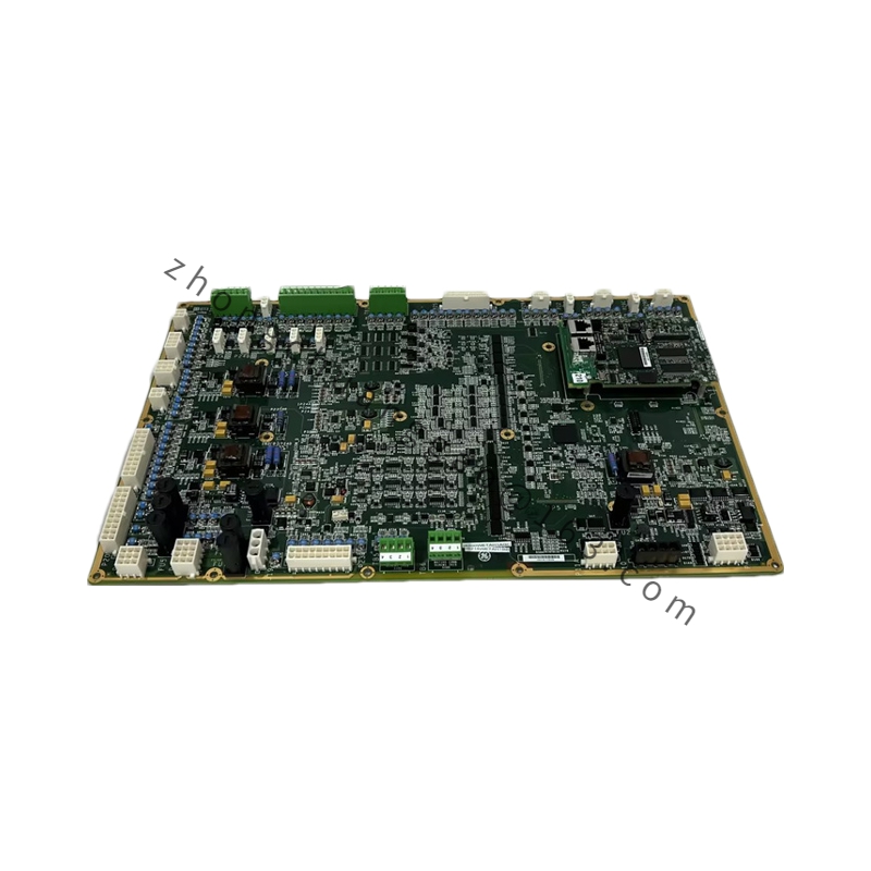
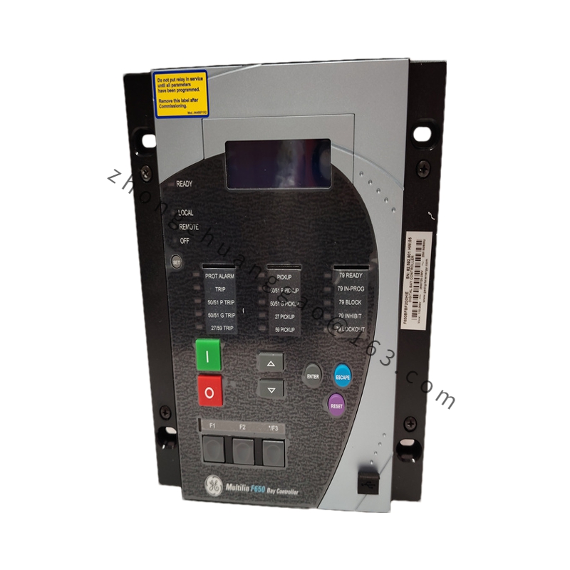
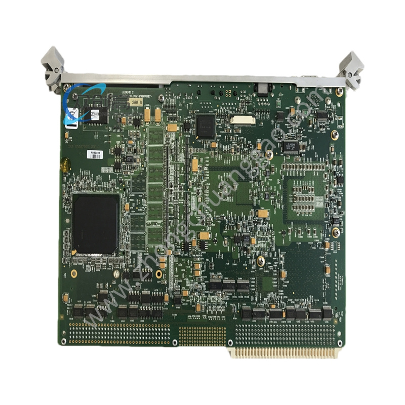
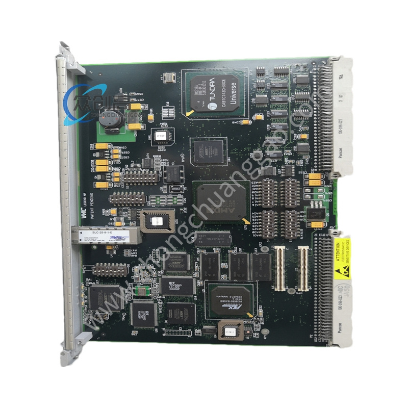
GE C994D128-096A224

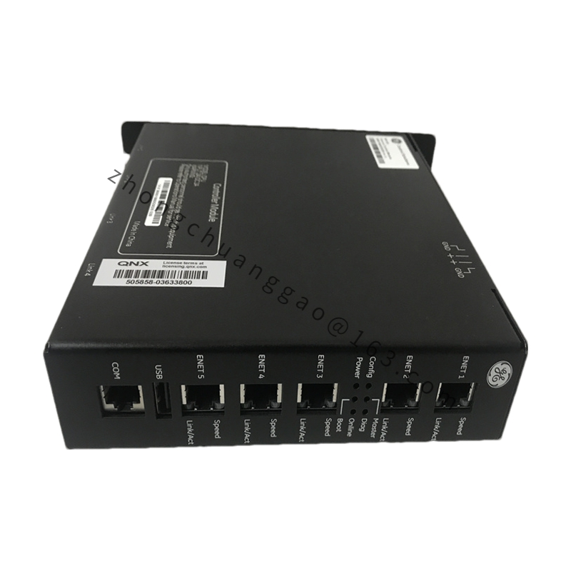
Product Introduction: The GE C994D128-096A224 is a speed and load control module in the GE Digital Energy C994D series, dedicated to speed control and load distribution of gas turbines and steam turbines. It is a core component of power plant governor systems. “C994D” denotes the C994D series speed/load controller; “128” is the functional code for speed control + load control; “096” represents hardware version/input configuration; “A224” is a specific configuration code for output type/communication.
Detailed content

Technical Specifications:
  • Series: C994D
  • Function: Speed control / Load control
  • Speed input: 4–20 mA or pulse signal (magnetic/electric or Hall-effect)
  • Speed measurement range: 0–6000 RPM (adjustable)
  • Load command input: 4–20 mA or 0–10 V DC
  • Valve position feedback: 4–20 mA (LVDT)
  • Valve position output: 4–20 mA (drives electro-hydraulic converter)
  • Control accuracy: ±0.1%
  • Response time: ≤ 100 ms
  • Communication interface: serial communication (RS-485/RS-232)
  • Power requirement: 24 V DC or 110/220 V AC/DC
  • Operating temperature: -10 °C to +55 °C
  • Protection rating: IP54 (panel mounting)
  • Certifications: UL, CSA, CE
Functional Features:
  • Speed control: receives speed signal, PID-adjusted valve command output
  • Load control: receives load command, controls unit output
  • Valve position control: closed-loop valve opening control
  • Speed droop rate adjustable (typically 3%–5%)
  • Acceleration/deceleration rate limiting
  • Valve position limits (maximum/minimum opening)
  • Cascade control mode supported
  • Field parameters set via keys or software
Material Composition:
  • Housing: cast aluminum alloy with powder coating (RAL 7035)
  • Front panel: brushed stainless steel
  • Internal PCB: FR-4 with conformal coating
  • Terminals: copper alloy with nickel plating
Structural Features:
  • 1/4 DIN (96 mm × 96 mm) panel cutout mounting
  • Front panel: 4-digit LED display + 4 push buttons
  • Rear panel: current input/output terminals + communication terminals + power terminals
  • DIN 35 mm rail mounting
Application Scenarios: Gas turbine control, steam turbine control, industrial governors, generator set governor systems.
Working Principle: The speed sensor signal is processed and compared with the setpoint. The PID controller outputs a valve position command, which drives the regulating valve via an electro-hydraulic converter, thereby changing steam/air intake to control speed and load. In load mode, it receives external load commands to directly control valve opening.
Installation Requirements:
  • 96 mm × 96 mm panel cutout
  • Use shielded cable for speed sensor signal lines
  • Use shielded twisted pair for valve position feedback LVDT signal lines
  • Connect power per terminal diagram, observing polarity
Usage Notes:
  • Speed signal must match controller input type (4–20 mA or pulse)
  • Valve command output must be amplified via electro-hydraulic converter to drive the oil servomotor
  • Control parameters (PID parameters, droop rate, etc.) must be tuned according to unit characteristics
  • Regularly calibrate speed measurement accuracy

You may also like