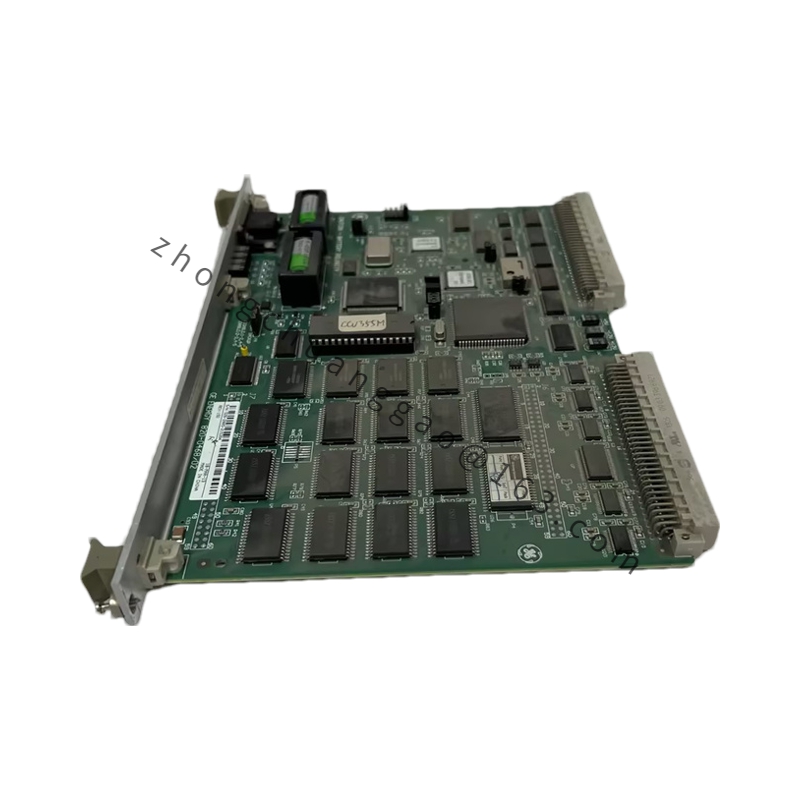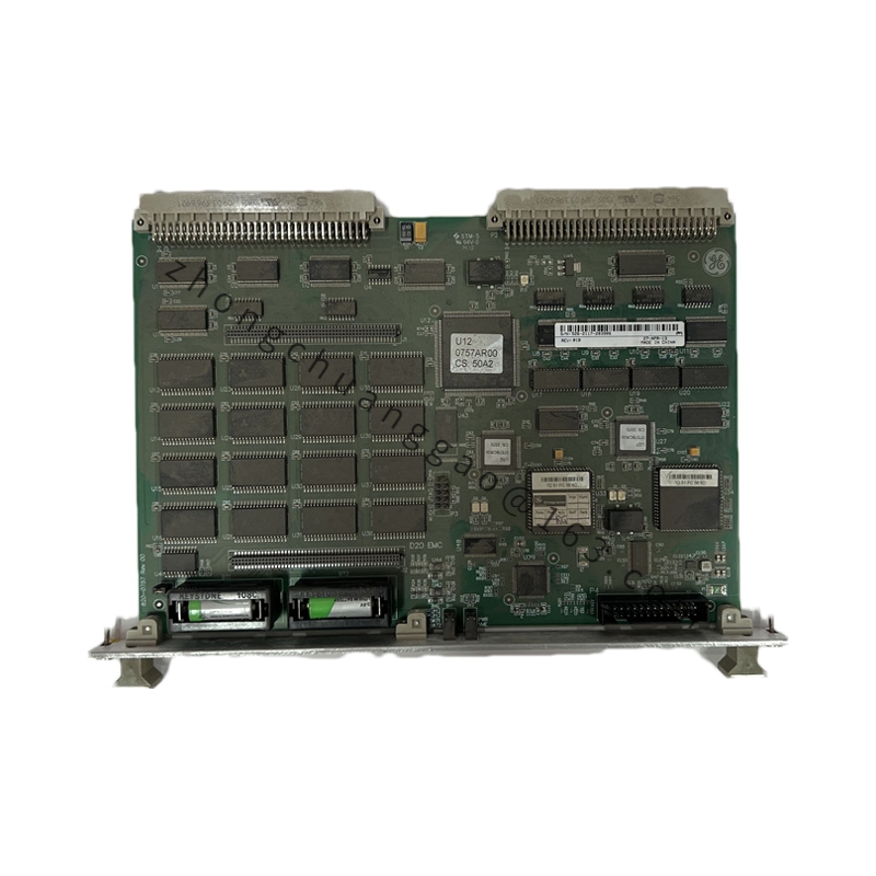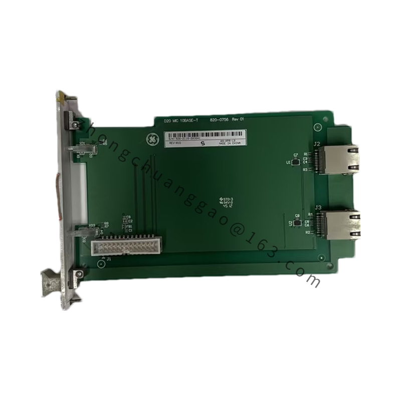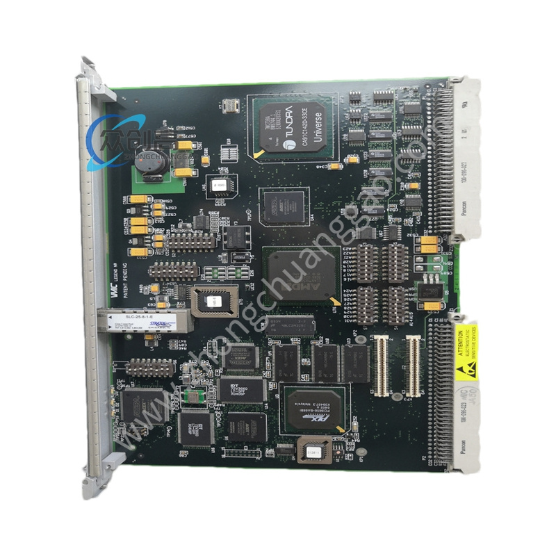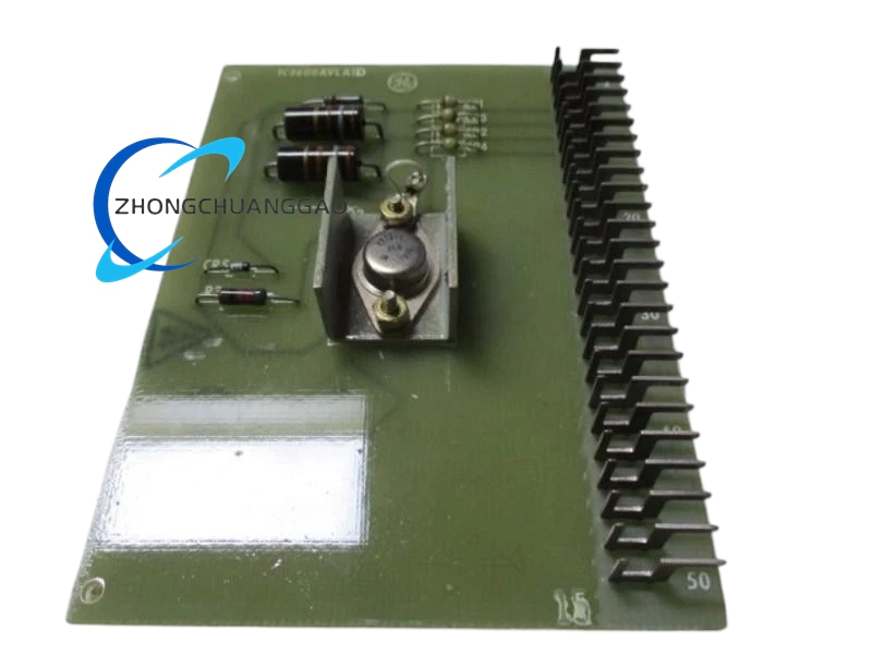
GE 994D128-0
Product Name: 994D Series Frequency / Power Controller Module (Multilin Digital Controller)
Product Introduction: The 994D128-0 is the frequency and power controller portion of GE’s 994D series multifunction digital controller family. Together with its counterpart 994D129 (synchrocheck controller), it forms a combined configuration for generator set synchronizing, frequency regulation, and power control. The “0” suffix denotes the base version.
Detailed content
Technical Specifications (994D128 Frequency / Power Controller):
- Function: Frequency regulation / power control
- Frequency input: 4-20 mA or pulse
- Power input: 4-20 mA (from power transducer)
- Frequency control accuracy: ±0.01 Hz
- Power control accuracy: ±1%
- Output: 4-20 mA (valve command)
- Power supply: 110 V / 220 V AC or DC
- Communication: RS-485 (Modbus)
- Protection rating: IP54
Combined Configuration (with 994D129 Synchrocheck):
- Synchrocheck functions: Voltage difference ≤ 10%, frequency difference ≤ 0.5 Hz, phase angle difference ≤ 10° (breaker close permit conditions)
- Voltage input: 110 V / 220 V AC or DC
- Frequency measurement range: 45-65 Hz
- Phase angle detection: 0°-360° (accuracy ±1°)
- Slip detection: 0.1-10 Hz/s (settable)
- Panel cutout: 96 mm × 96 mm
- Event recording and fault waveform capture supported
Functional Features:
- 994D128: Receives frequency and power signals, regulates unit output to maintain stable grid frequency
- 994D129: Automatically checks synchronism conditions (voltage, frequency, phase angle) before issuing breaker-close permission
- RS-485 communication for remote monitoring
- Event logging and fault waveform recording
- IP54 front panel protection
Material Composition:
- Housing: Flame-retardant ABS (UL94 V-0)
- Front panel: Polycarbonate transparent cover
- Terminals: Nickel-plated copper alloy
Structural Characteristics:
- 96 mm × 96 mm panel cutout mounting
- Front panel with LED display and push-buttons
- Rear panel wiring terminals
- Combined 994D129 + 994D128 configuration for complete synchronizing and control
Working Principle: The 994D128 receives frequency and power feedback signals (4-20 mA or pulse). Its internal controller computes the required valve command (4-20 mA output) to regulate the prime mover, maintaining grid frequency stability. In the combined package, the 994D129 continuously monitors voltage, frequency, and phase angle of the generator versus the bus; when all three parameters are within the pre-set limits (voltage difference ≤ 10%, frequency difference ≤ 0.5 Hz, phase angle difference ≤ 10°), it issues a breaker-close permit.
Installation Requirements: Panel cutout of 96 mm × 96 mm. Use shielded cable for voltage and frequency signal wiring. Use shielded twisted-pair cable for RS-485 communication with proper termination resistors. Connect power per the rated 110 V / 220 V AC or DC supply.
Usage Precautions: The synchrocheck parameters (voltage difference, frequency difference, phase angle limits) must be set according to the specific grid requirements. The power signal to 994D128 must come from a calibrated power transducer. Periodically test the synchrocheck function to verify correct operation. The RS-485 communication address must be consistently planned with the host system. Because this module is part of a combined 994D129 + 994D128 configuration, verify both units’ firmware and configuration compatibility before deployment.