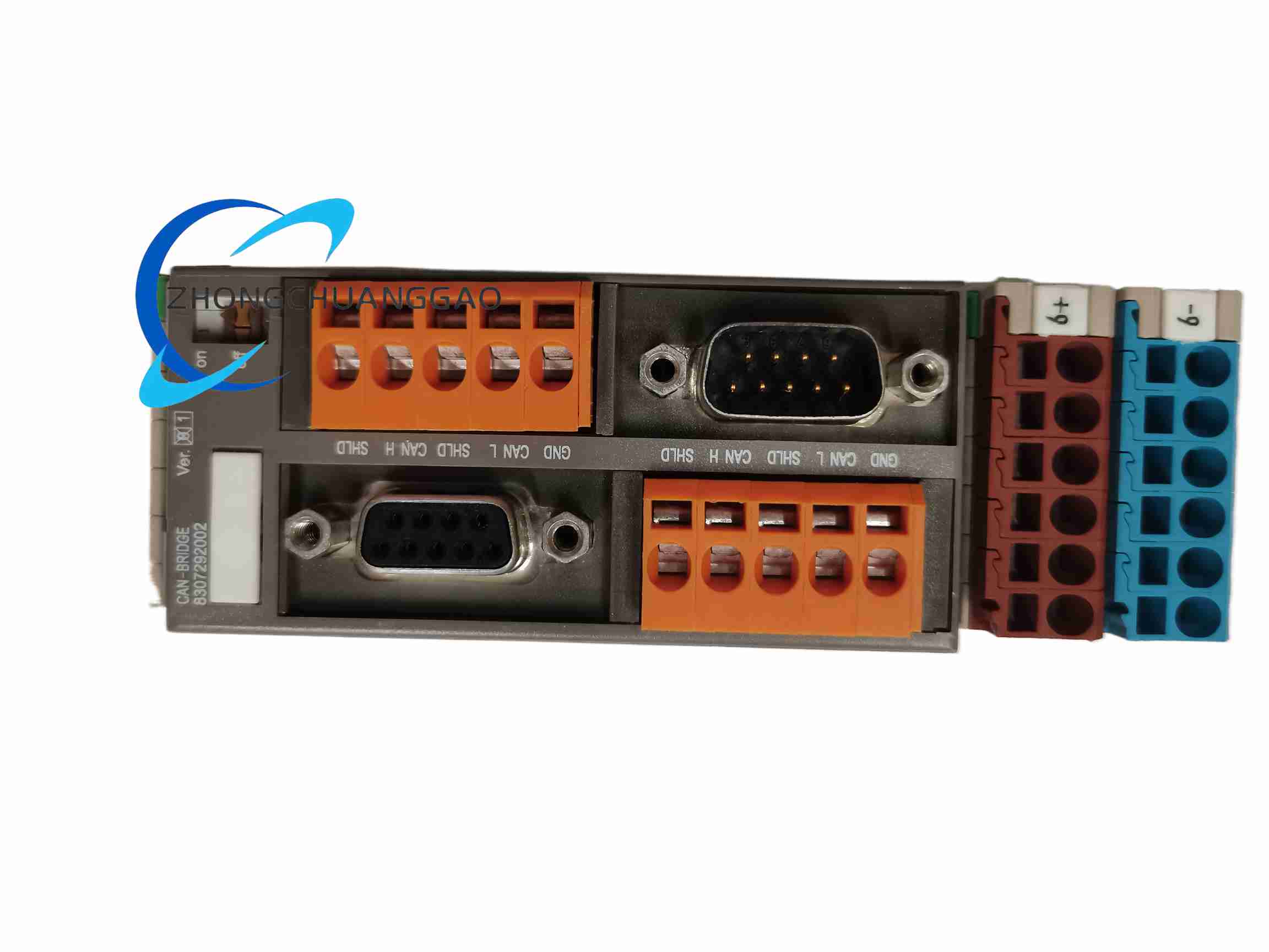
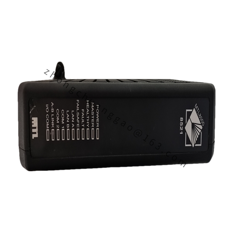
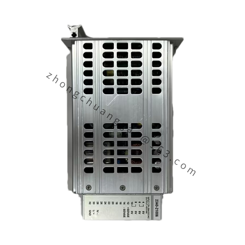
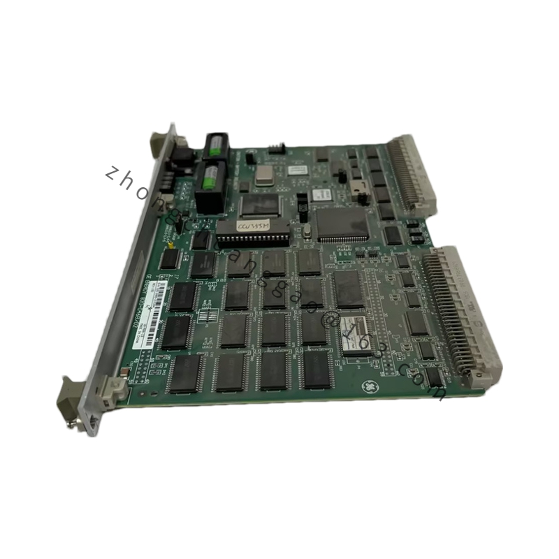
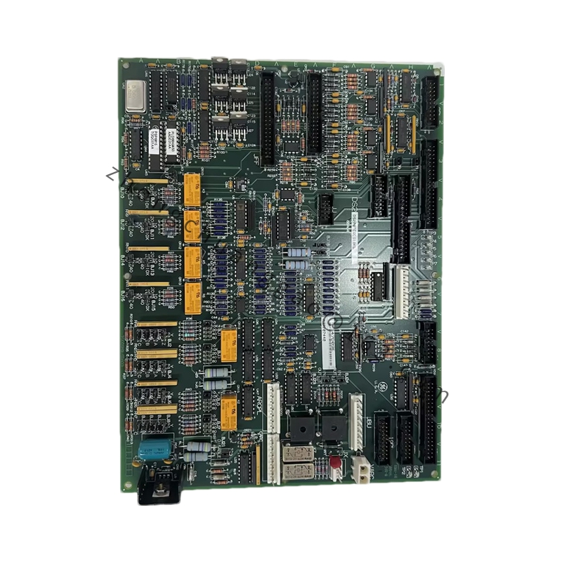
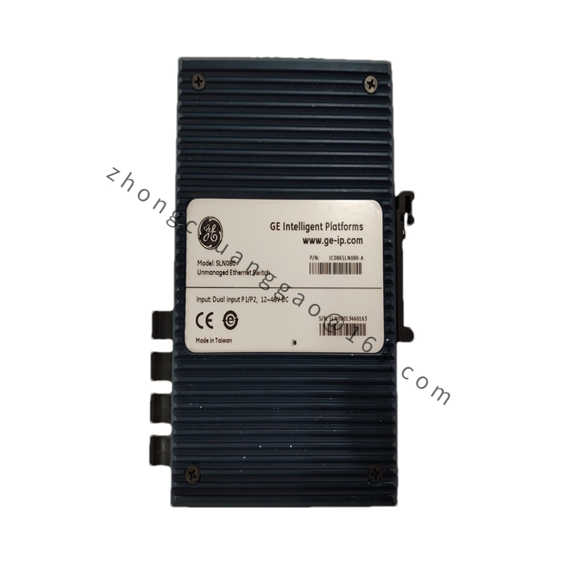
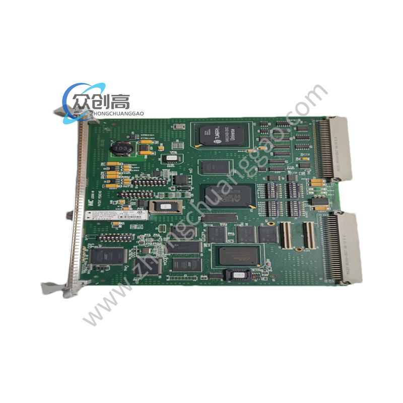
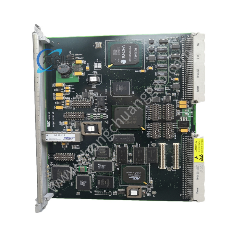
Technical Specifications: CAN interface; operating voltage 24 V DC; data rate up to 1 Mbps; onboard buffer around 256 bytes on documented variants; operating temperature -40 to +85 °C; dimensions approximately 100 × 60 × 30 mm; weight approximately 0.3 kg; CE, UL and RoHS compliance on documented variants; RJ45 or CAN connector options depending on host configuration.
Functional Features: CAN frame transfer and bridging; error detection and correction support; configurable node parameters through engineering software; integration with industrial controllers; status indication for power, communication and fault conditions.
Performance Parameters: 1 Mbps maximum CAN throughput; -40 to +85 °C continuous operating range; 24 V DC nominal input; low-latency buffering for short control messages; industrial EMC and temperature endurance suitable for cabinets, vehicles or outdoor enclosures when properly housed.
Material And Structure: Metal or molded industrial enclosure depending on variant; PCB with conformal coating where specified; DIN-rail or panel mounting according to the host cabinet design; CAN transceivers with termination and protection components.
Working Principle: The module terminates the CAN physical layer, manages identifiers, message filtering and buffering, and forwards validated frames between the CAN network and the connected controller or upper network. Built-in diagnostics report bus errors, node absence and buffer overflow conditions.
Installation Requirements: Mount in a grounded control cabinet with adequate ventilation; use shielded CAN cable; set termination resistors only at both physical ends of the bus; separate signal wiring from high-voltage power cables; confirm 24 V DC supply capacity and polarity before energizing.
Application Scenarios: Generator control networking, factory CAN device integration, mobile machinery diagnostics, powerplant auxiliary communication, retrofit of legacy CAN instruments and multi-vendor automation interconnection.
Usage Precautions: Do not exceed 24 V DC supply. Do not connect incompatible CAN baud rates on the same bus without proper bridge configuration. Verify termination and node IDs before commissioning. Protect the module from electrostatic discharge and moisture ingress if the enclosure is not sealed.