Digital guide

You are here:

GE 7VWCS086CD01

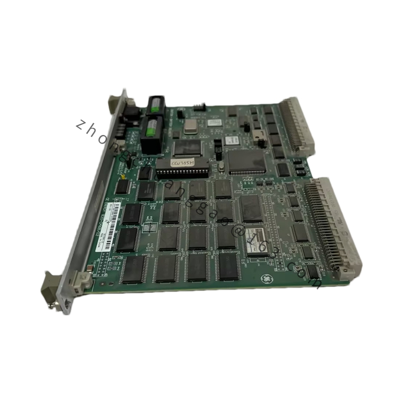
Product Name: GE Fanuc 7VWCS086CD01 16-Channel Digital Input Module
Product Overview: The 7VWCS086CD01 is a 16-channel digital input module for the GE Fanuc Series 90-30/70 PLC system. It is used to collect field discrete signals (such as buttons, limit switches, relay contacts, proximity switches, etc.), converting external 24 VDC signals into logic signals that can be processed internally by the PLC.
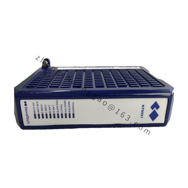
Detailed content

Technical Specifications:
  • Brand: GE Fanuc
  • Model: 7VWCS086CD01
  • Series: Series 90-30/70
  • Channels: 16 channels
  • Input Voltage: 24 VDC (rated)
  • Input Type: Sink/Source selectable via jumper or DIP switch on-site
  • Input Current: Approximately 7 mA per channel at 24 VDC
  • ON Voltage Range: 15 VDC ~ 30 VDC (Logic “1”)
  • OFF Voltage Range: 0 VDC ~ 5 VDC (Logic “0”)
  • Isolation: Optocoupler isolation, channel-to-channel isolation, 500 VDC
  • Response Time: ON→OFF < 1 ms; OFF→ON < 1 ms (typical)
  • Filter Time: Software configurable, 0 ~ 12.8 ms
  • Supply Voltage: 24 VDC (bus-powered)
  • Power Consumption: Approximately 2 W
  • Front Panel: One group of 8-bit LED status indicators per 8 channels
Functional Features:
  • Sink/Source input switchable via jumper or DIP switch on-site, no module replacement needed
  • Independent optocoupler isolation per channel for strong anti-interference capability
  • Software-configurable input filter time to eliminate mechanical jitter
  • Some channels can be configured for high-speed counting input function
  • Front-panel LEDs display real-time on/off status of each channel
Structural Features:
  • Standard Series 90-30/70 module dimensions
  • Front Panel: 16-bit LED indicators (divided into two groups of 8 bits each), DIP switch group
  • Bottom: Genius bus connector
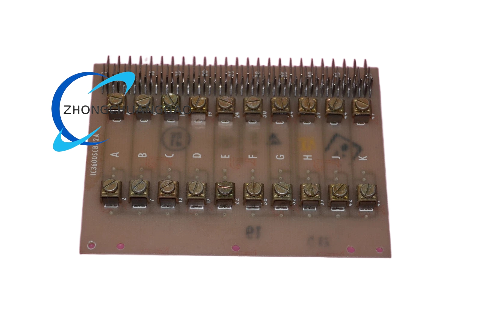
  • Terminals: 16 groups of independent terminals, screw compression
  • Housing Material: Flame-retardant engineering plastic (UL94 V-0)
Installation Requirements:
  • Install in Series 90-30/70 rack
  • Use shielded cable for field signal lines, with shield single-point grounded on the PLC side
  • Terminal maximum conductor size: 22 AWG (0.33 mm²) ~ 14 AWG (2.08 mm²)
  • Sink/Source configuration must match the field sensor type
Usage Notes:
  • Strictly prohibit input voltage exceeding 30 VDC, otherwise the optocoupler will be damaged
  • Inductive load signals require freewheeling protection
  • Operating environment temperature: 0°C ~ 60°C
  • Long-unused channels should be shorted or connected to a fixed level
Application Industries: Manufacturing production lines, packaging machinery, material handling, automotive welding lines, food and beverage production lines.

You may also like