Digital guide

You are here:

GE 750-P5-G5-S5-HI-A20-R-E-H

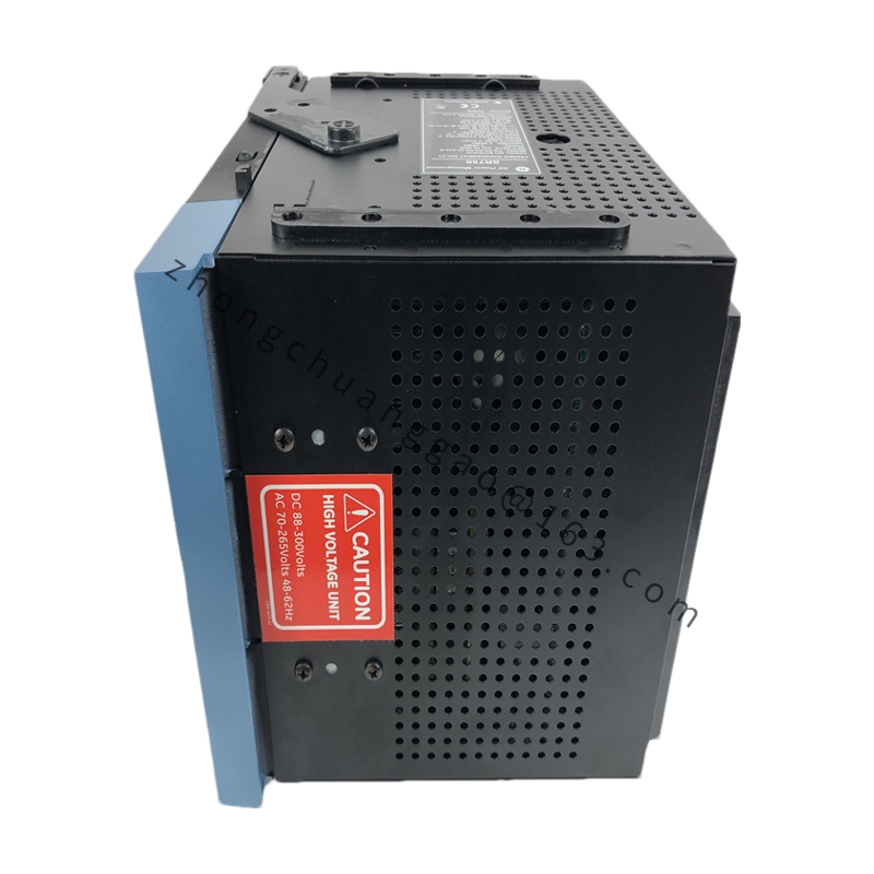
Product Name:​ GE 750 Series Feeder Management / Overcurrent Protection Relay (SR750)
Introduction:​ A high-performance electrical protection relay from GE’s 750-series transformer and feeder protection system. It monitors phase current, zero-sequence current, and sensitive ground current, and provides comprehensive overcurrent protection, metering, and I/O for medium-voltage distribution systems.
Detailed content

Order-Code Breakdown:
  • 750​ – 750 Transformer/Feeder Protection System
  • P5​ – 5 A phase current inputs
  • G5​ – 5 A zero-sequence current input
  • S5​ – 5 A sensitive ground current input
  • HI​ – Power supply: 88–300 V DC or 70–265 V AC @ 48–62 Hz
  • A20​ – Eight 4–20 mA analog outputs
  • R​ – Red breaker-closed LED
  • E​ – Enhanced display (larger LCD, improved keypad)
  • H​ – Harsh Chemical Environment option
Dimensions:​ 21.5 × 23 × 25 cm
Key Features:
  • Adjustable trip settings and time-delay curves for flexible protection coordination
  • Built-in accurate metering—eliminates auxiliary metering devices and reduces cost
  • I/O monitoring to improve uptime of auxiliary equipment
  • IRIG-B time synchronization, event reports, waveform capture, and data logger for faster troubleshooting
  • Draw-out (withdrawable) construction for minimized replacement time
  • Built-in simulation features to simplify testing
  • Flash memory for field firmware upgrades
  • Communication: DNP & Modbus protocols; optional 10 MB Ethernet port
  • Full analog I/O and complete metering including demand & energy
Working Principle:​ Continuously samples phase, zero-sequence, and sensitive ground currents. When measured currents exceed pre-programmed thresholds, the relay issues trip commands per the configured time-delay curves, while simultaneously recording events and waveform data for post-incident analysis.
Typical Applications:
  • Medium-voltage switchgear in utility substations (13.8 kV–69 kV distribution feeders)
  • Industrial plant distribution systems requiring comprehensive protection and analog output integration
  • Bus protection schemes needing voltage inputs and multiple protection functions
  • Transformer backup protection with voltage-restrained overcurrent and directional elements
  • Retrofit replacements for legacy electromechanical relays (GE MIF / MIF II, Multilin 239, 735/737)
Installation & Usage Notes:
  • Mount the relay in a control panel or enclosure per applicable electrical codes and safety standards.
  • Critical field rule:​ Verify the power-supply code before wiring. “HI” = 88–300 V DC or 70–265 V AC. Never connect 24 V DC to an “HI” relay—it will fail to power up and may damage the internal power supply. Measure available control power at the cabinet before energizing.
  • Keep G5 (zero-sequence) and S5 (sensitive ground) current inputs separate; they serve different protection schemes and are mutually exclusive in many applications. Do not wire a single core-balance or window CT to both.
  • Configure protection thresholds, delay times, and communication settings via the enhanced front-panel interface or via DNP/Modbus.

You may also like