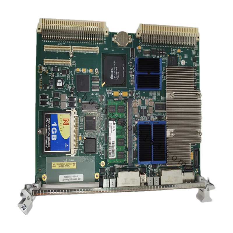
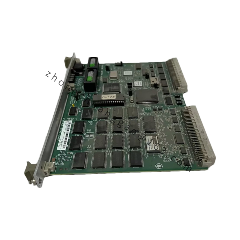
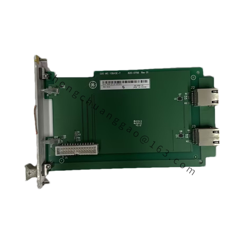
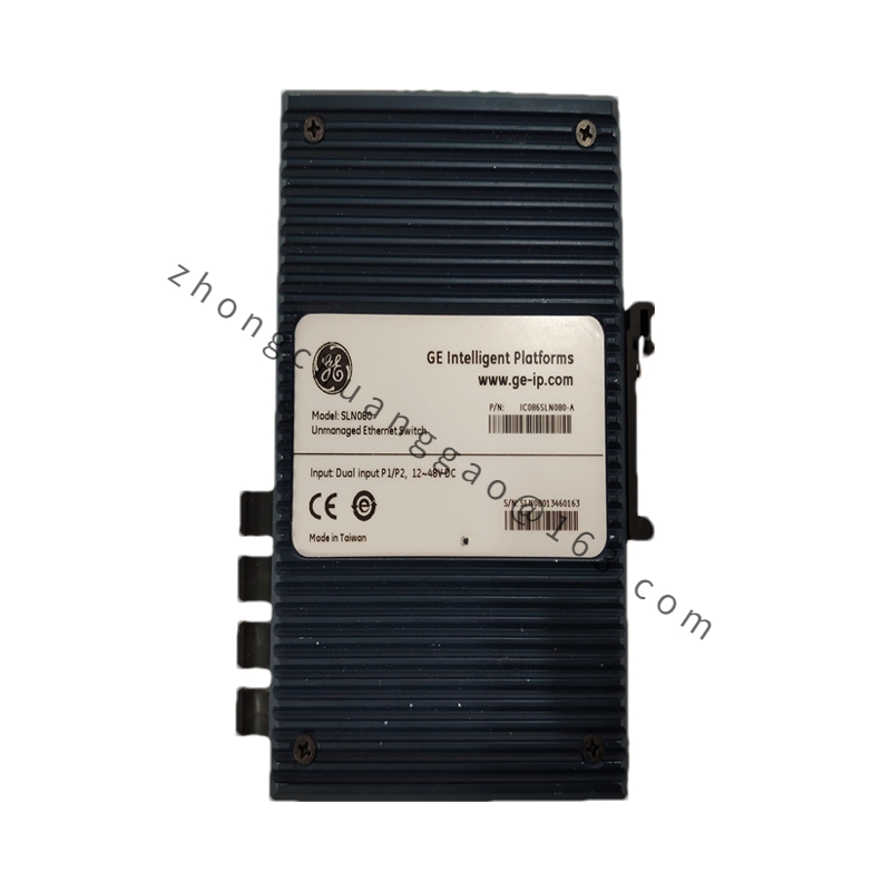
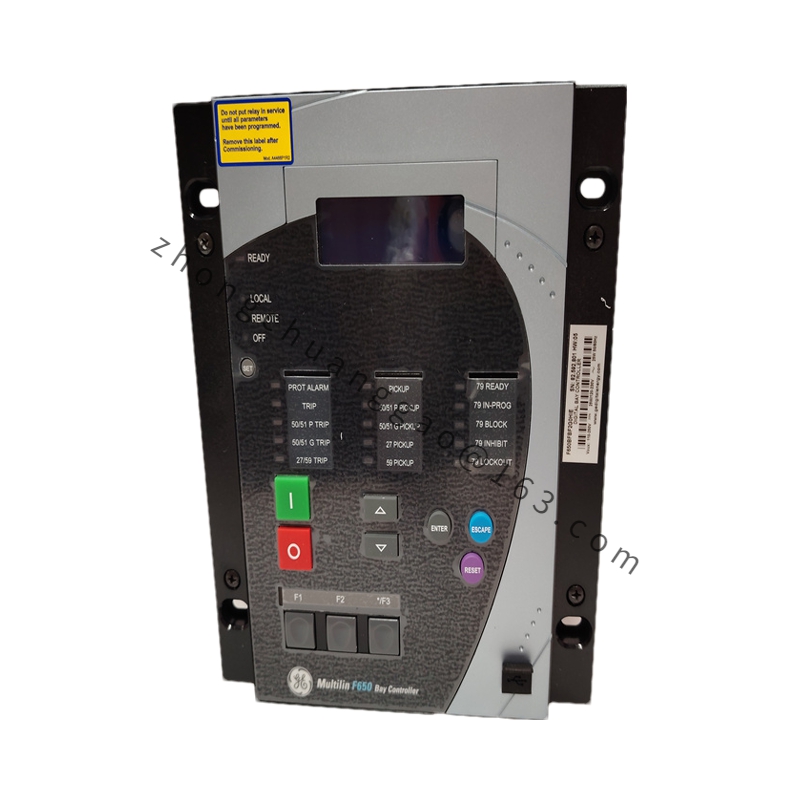
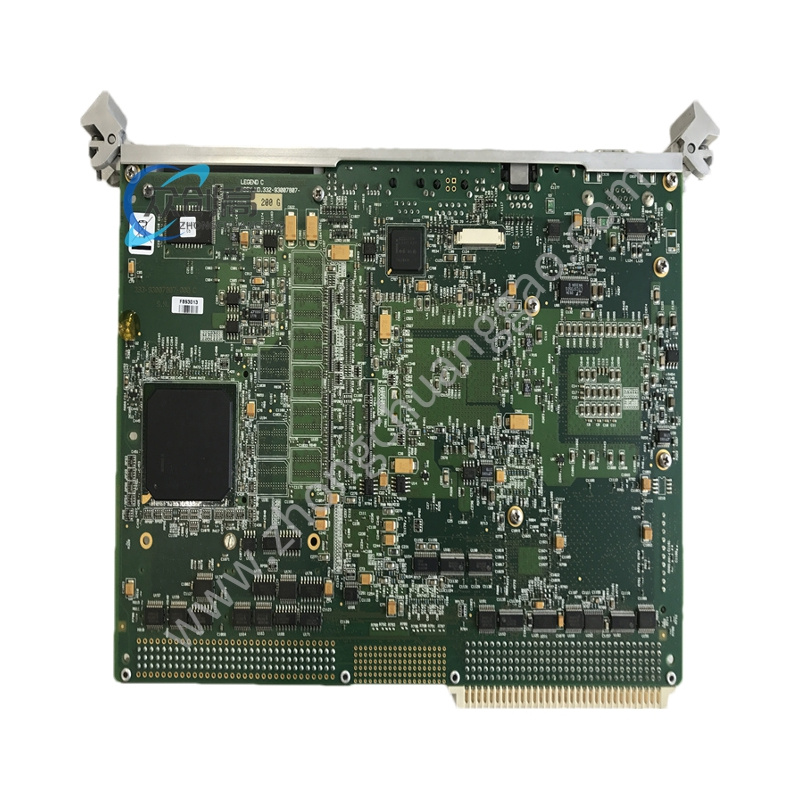
Product Name: GE 55A213937P550B – Multi-function I/O Module for Speedtronic Mark V/VI Gas Turbine Control System
Introduction: A versatile analog/digital I/O processing module used in GE’s Speedtronic Mark V and Mark VI gas turbine control systems to acquire field process variables and output control signals to actuators. (Note: some public catalogs also list “55A213937P550B” as a medium-voltage fuse; the I/O module identification is consistent with the 55A-series part numbering for Mark V/VI modules. Verify the physical part and nameplate marking at delivery.)
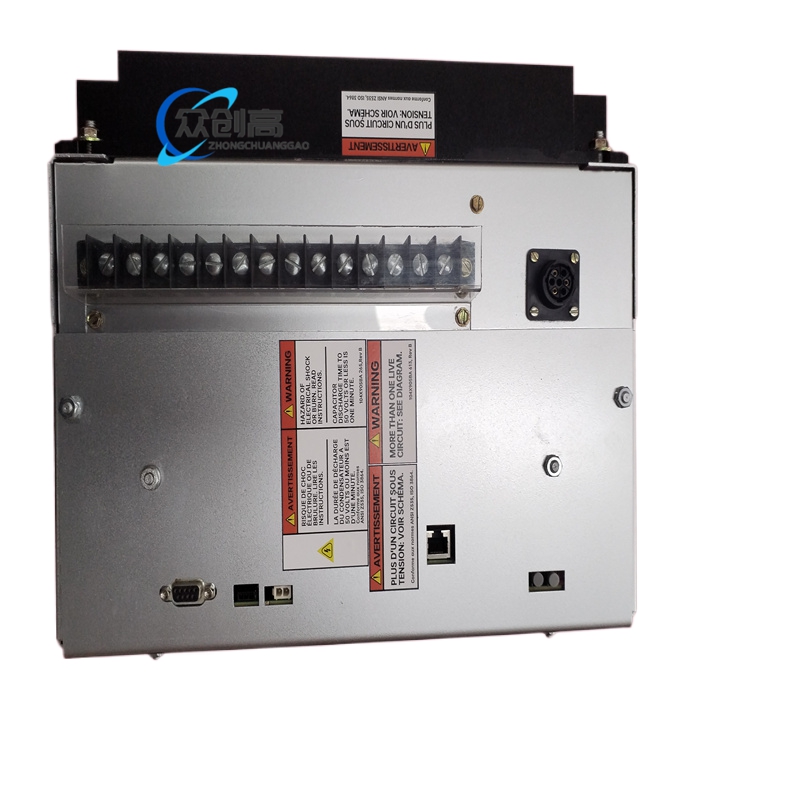
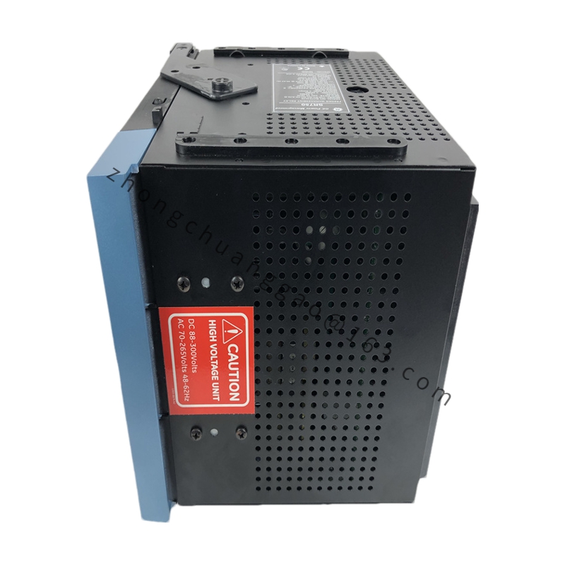
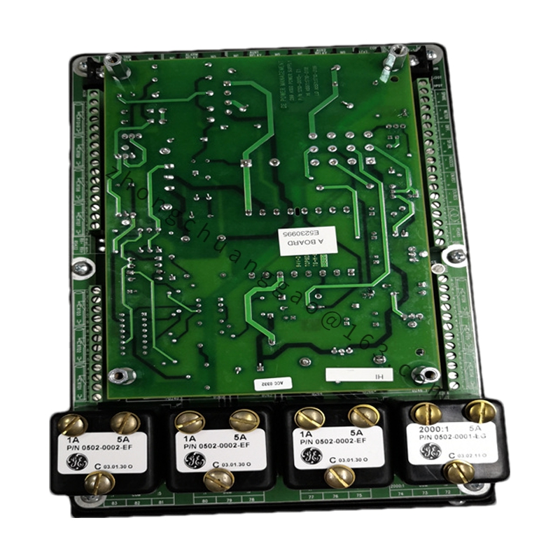
Structural Features: Standard Mark V/VI cabinet mounting dimensions; front-panel channel-status LEDs (one green/red pair per 4 channels); rear SRTP bus connector plus signal terminal strip; top positioning rail clip; bottom ventilation openings.
Working Principle: The module communicates with the Mark V/VI controller over the SRTP high-speed redundant bus. Field sensors connect to the terminal strips; analog signals pass through conditioning, A/D conversion (16-bit), and isolation before being placed on the bus. Control commands from the controller are converted via D/A and relay outputs to drive field actuators.
Application Scenarios: Gas and steam turbine control in power generation; process variable acquisition and actuator control in Mark V/VI-based automation systems.
Installation & Usage Notes:
Mount in a Mark V/VI control cabinet with proper grounding.
Before replacement, photograph all jumper and wiring positions; replicate exactly on the new module.
Observe ESD precautions. Verify SRTP bus address and redundancy configuration match system design.
For RTD/TC inputs, confirm cold-junction compensation and wire-break detection are enabled per the application.
Because the module supports hot-swap in a redundant configuration, ensure the system is in a safe state and the standby module is healthy before removing the active module.