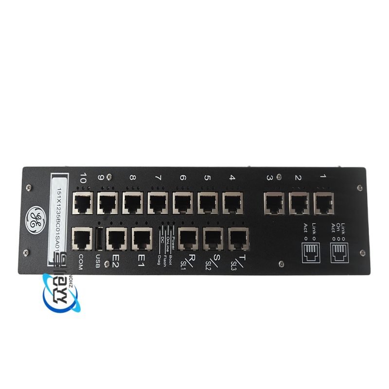
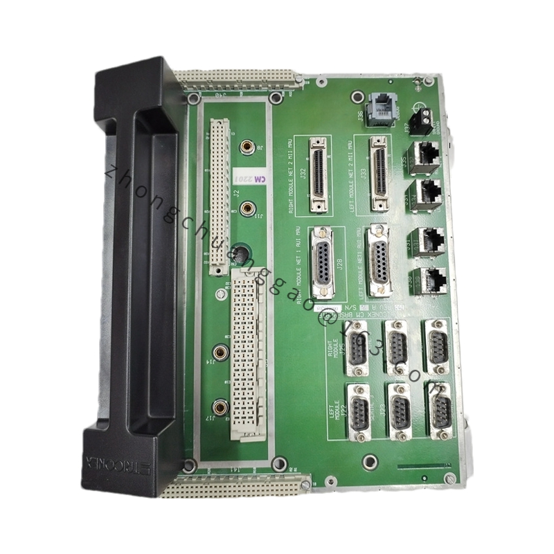
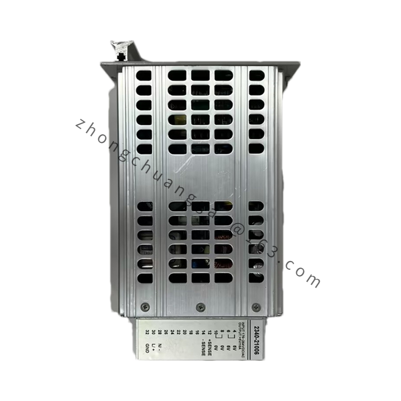
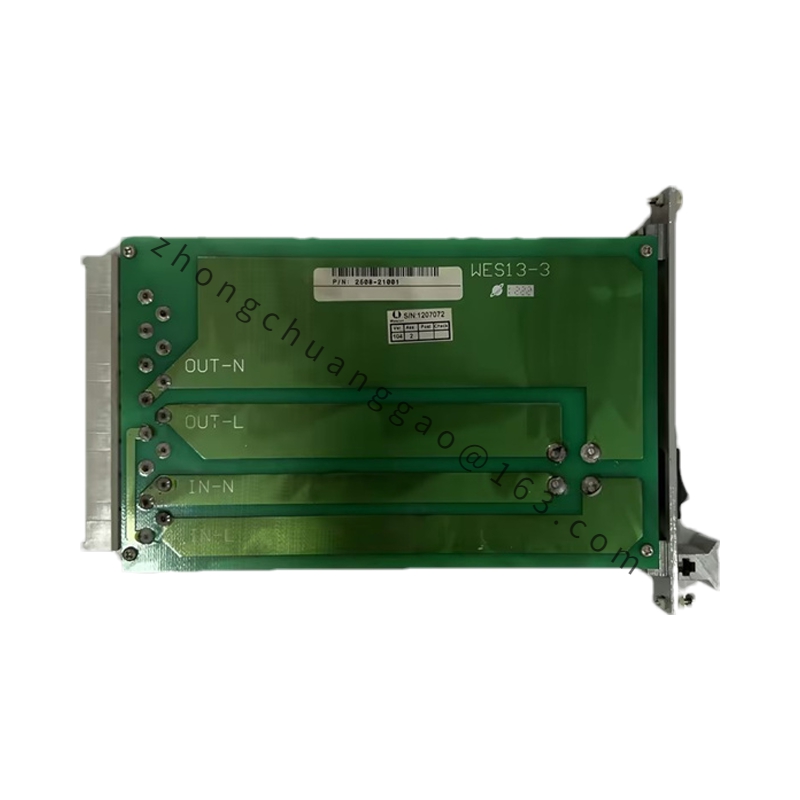
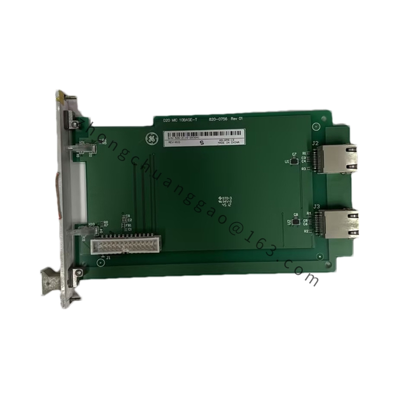
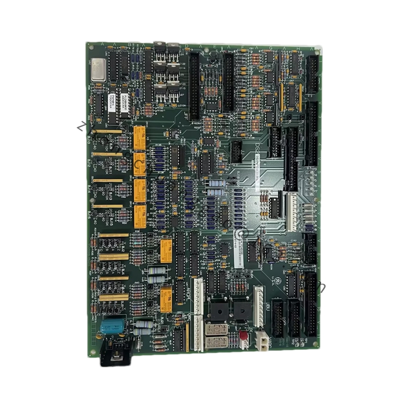
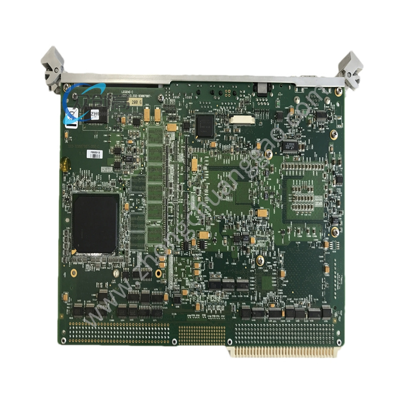
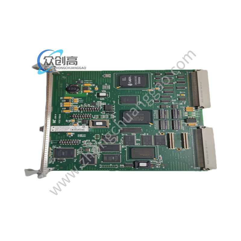
Product Name: GE 531X Series Power Control & Signal Distribution Board (PCSA I/O Pack)
Product Introduction: A power control, analog output amplification, and isolation protection board within GE’s EX2000 / DC2000 / AC2000 and Mark VIe drive control systems. It amplifies low-level control signals from the control system to drive field solenoid valves, contactors, or braking units.
Response Time: ≤ 5 ms for bus over/under-voltage detection and output inhibit
Analog Output: 4–20 mA active, load ≤ 500 Ω, accuracy ±0.1 %
Environmental: 3C3 corrosion-gas class, 1 g vibration endurance
Hot-Swap: Supported under Mark VI TMR architecture
Functional Features: Online hot-swap replacement; multiple LED status indicators (power, fault, per-channel state); integrated MOV surge suppression and freewheeling diodes for inductive load protection; configurable control inputs.
Structural Features: Single-slot plug-in PCB; front-end Phoenix terminal block; conforms to GE 531X backplane mechanical dimensions; front panel fixing screw holes.
Working Principle: Backplane receives control logic level → internal signal conditioning & power amplification → isolated drive output to field load; simultaneously samples output current/voltage feedback to protection comparators.
Application Scenarios: GE EX2000/DC2000/AC2000 high-power drives, Mark VIe turbine control systems — driving trip solenoids, cooling fans, contactors, and braking units.
Installation & Usage Notes: Install in designated I/O slot of GE EX2000/DC2000 standard cabinet; tighten panel screws and ensure full backplane connector engagement. For high-humidity regions (>85 % RH), perform 500 MΩ insulation test every two years. Record DIP switch and jumper settings before replacement; never operate output terminals without flyback suppression (e.g., solenoid freewheeling diode) to avoid reverse-EMF damage.