GE 531X196DFAACG1
Product Overview: The 531X196DFAACG1 is part of GE’s 531X series of PCB boards used in general-purpose drive systems, including DC-300, AC-300, and AF-300 drives. The “DFA” designation indicates a Digital Feedback Adapter. The “ACG1” revision provides multi-mode feedback inputs, enhanced signal filtering, extended temperature range, marine-grade conformal coating, screw-type terminals, and per-channel diagnostic LEDs. It conditions and converts digital and analog feedback signals from encoders, resolvers, and analog sensors for precise closed-loop speed, position, and torque control.
Detailed content
Technical Specifications:
- Product Type: Digital / Analog Feedback Interface Board
- Digital Encoder Inputs: A, B, Z (differential or single-ended) up to 500 kHz
- Resolver Inputs: Sine, cosine, reference (differential)
- Analog Sensor Inputs: 4 channels (0–10 V, ±10 V, 0–20 mA, 4–20 mA, selectable)
- ADC Resolution: 12-bit (analog), 16-bit (digital/encoder)
- Input Impedance: >100 kΩ (voltage), 250 Ω (current)
- Filtering: Enhanced low-pass filter on all channels (ACG1 revision)
- Accuracy: ±0.1% of full scale (analog)
- Isolation: 2,500 Vrms between feedback inputs and drive logic
- Diagnostics: Signal presence detection, over-range/under-range detection
- Terminal Type: Screw-type (24–12 AWG)
- Connectors: One 26-pin header to regulator board; one 20-position terminal block for field wiring
- Mounting: 4 × M4 holes (standard GE rack footprint)
- Power Supply: +5 V DC and ±15 V DC from regulator board
- Operating Temperature: -20°C to 70°C (extended)
- Conformal Coating: Marine-grade (moisture and corrosion resistant)
Structural Characteristics:
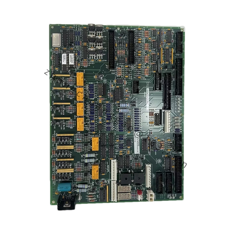
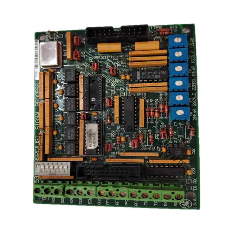
- PCB with transformer assembly featuring four surface wires (two red, two white) connecting at points R1, R2, W1, W2
- Surface wiring connecting capacitors and metal film resistors in the upper-left corner
- 31-pin connector plus five snap-in connectors
- Drill holes in each corner for mounting
Functional Features:
- Multi-mode feedback: Configurable via jumpers for encoder, resolver, or analog sensor inputs
- Enhanced filtering reduces noise for stable low-speed control
- Marine-grade conformal coating protects against humidity, salt spray, and corrosive gases
- Screw terminals resist loosening in high-vibration environments
- Per-channel diagnostic LEDs simplify troubleshooting
- 16-bit digital input supports high-resolution encoder/resolver position data
- 2,500 Vrms galvanic isolation protects the regulator board
- Plug-and-play direct replacement for earlier DFA revisions
Performance Parameters:
- Extended temperature range: -20°C to 70°C
- 16-bit encoder resolution for precision positioning
Application Cases:
- CNC machines: High-accuracy axis positioning with encoder feedback
- Offshore platforms: Resolver feedback for motor speed control in corrosive environments
- Mining conveyors: Analog speed reference in high-vibration environments
Working Principle: The board receives raw feedback signals from encoders, resolvers, or analog sensors, conditions them through enhanced filtering, converts analog signals to digital via 12-bit ADC (and digital signals to 16-bit resolution), and presents the processed feedback to the drive’s regulator board via the 26-pin header. Jumper configuration selects the appropriate feedback mode.
Installation Requirements:
- Mount via four M4 holes in standard GE rack footprint
- Ensure +5 V DC and ±15 V DC power from regulator board
- Use screw terminals (24–12 AWG) for secure field wiring
- Properly seat 26-pin header to regulator board
Usage Notes:
- Configure jumpers for correct feedback device type (encoder/resolver/analog)
- Verify signal presence LEDs during commissioning
- Marine-grade coating permits use in humid and corrosive environments