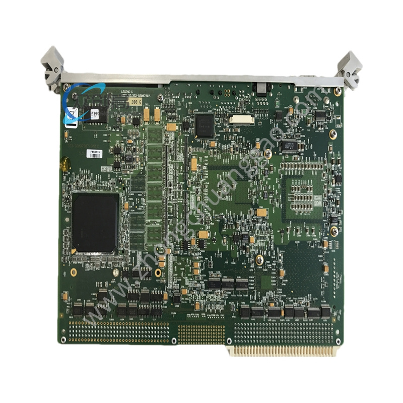
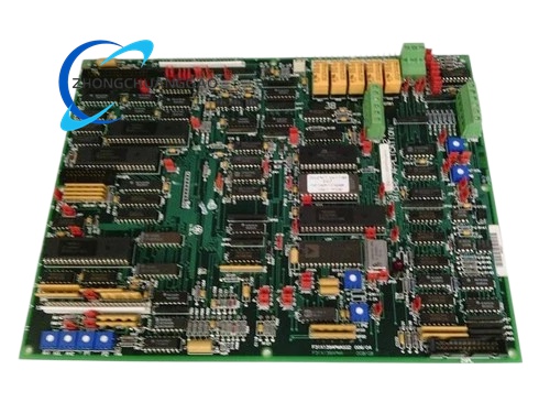
GE 531X139APMARM7
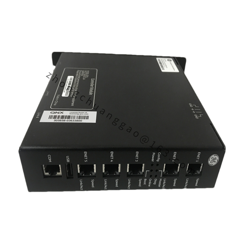
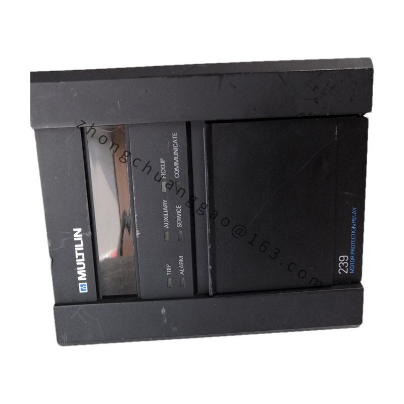
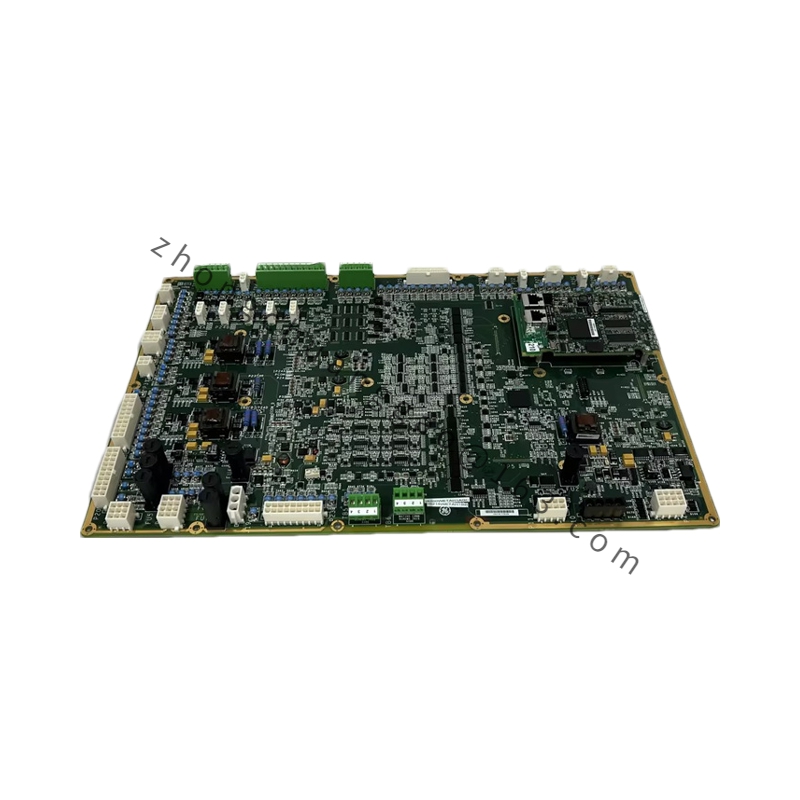
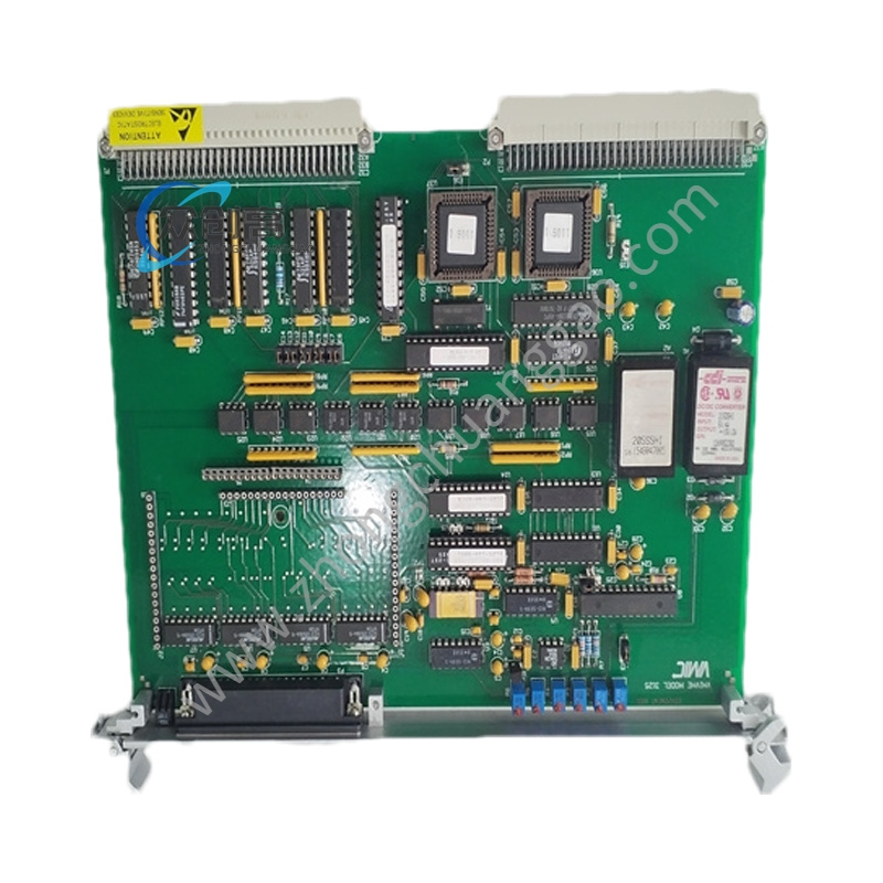
Product Description: This is a critical power distribution and communication backplane module manufactured by GE Automation and Controls for use in the GE Series 90-70 programmable logic controller platform. The module serves as the backbone of the PLC rack by receiving external main power converting it into multiple regulated DC voltages required by the various processor I/O and communication modules installed in the same rack, while simultaneously providing the high-speed parallel bus that interconnects all modules for data exchange. It is an essential infrastructure component in large-scale distributed control systems where reliability and signal integrity are non-negotiable.
Detailed content
Technical Specifications: Input power 120 or 240 volts AC single phase or 240 volts AC two phase selectable, DC output rails 5 volts at 10 amperes and 24 volts at 5 amperes simultaneously, maximum total DC load capacity 15 amperes across all output rails, bus bandwidth 100 megabits per second for module-to-module data transfer, compatible with all GE Series 90-70 processor communication and I/O modules, redundant power supply configuration supported with automatic switchover in under 10 milliseconds, physical format 9-slot vertical backplane with standard 9.5 by 44 millimeter module pitch.
Functional Features: Over-current protection on each output rail with electronic fusing and automatic reset after fault clearance, power supply health monitoring with alarm output to the processor module when any rail voltage deviates beyond 5 percent, bus signal integrity enhancement through impedance-matched trace routing and termination resistors on all bus lines, hot-standby redundancy input allowing a second identical power supply module to provide uninterrupted power if the primary fails, integrated watchdog circuit that forces processor reset if bus communication becomes corrupted for more than 500 milliseconds, diagnostic LEDs on the front panel indicating status of each voltage rail and bus activity.
Application Scenarios: Primary deployment in GE Mark VI and Mark VIe turbine control systems for power generation plants where uninterrupted control is a safety and regulatory requirement, used in GE DCS systems controlling chemical process units refineries and pipeline compression stations, applied in water and wastewater treatment plants for SCADA-integrated process control of pumping filtration and disinfection systems, deployed in oil and gas pipeline SCADA systems for compressor station and valve control, also used in GE Intelligent Platforms systems for large manufacturing facilities including automotive stamping presses and paper mills.
Performance Parameters: DC output voltage regulation better than plus or minus 1 percent under full load conditions, bus signal propagation delay less than 0.2 milliseconds between any two modules in the rack, power supply efficiency greater than 85 percent at full load minimizing heat generation, operating temperature range 0 to 60 degrees Celsius with 2 percent per degree derating above 50 degrees, ambient humidity 5 to 95 percent non-condensing, altitude rating up to 2000 meters with no derating, vibration tolerance 5g peak at 10 to 500 hertz per IEC 60721-3-3 for harsh industrial environments.
Material Composition: Backplane PCB manufactured from 4-layer high-Tg FR-4 laminate with 2.0 millimeter thickness for mechanical rigidity, copper bus traces plated with 1 ounce electroless nickel immersion gold for superior conductivity and corrosion resistance, power conversion section uses toroidal inductors and electrolytic capacitors rated for 105 degrees Celsius and 5000 hour lifetime, module frame constructed from 16-gauge galvanized steel with electrostatic powder coating, terminal blocks use high-current tin-plated copper bars rated for 30 amperes continuous, all internal connectors are press-fit gold-plated pins for vibration-proof electrical contact.
Structural Features: Standard 9-slot vertical rack configuration measuring approximately 400 millimeters wide by 350 millimeters tall by 250 millimeters deep, modular card guides on each slot for positive module retention with tool-less ejection levers, independent AC power input terminal block located at the bottom rear with dedicated ground lug, front panel houses seven LED indicators showing power status per rail plus bus activity and fault conditions, top and bottom ventilation slots provide natural convection airflow through the power conversion section, optional fan tray available for forced air cooling in high-ambient-temperature installations, DIN rail mounting holes on rear for cabinet installation in 19-inch standard relay racks.
Working Principle: External AC mains power enters through the input terminal block and passes through an electromagnetic interference filter then a bridge rectifier to produce raw DC. This DC is fed into multiple switched-mode power supply circuits that regulate and isolate the output to produce precise 5 volt and 24 volt DC rails. These regulated voltages are distributed to each module slot through dedicated copper bus bars on the backplane PCB. Simultaneously a high-speed parallel data bus runs across all module connectors allowing the processor module to exchange data with every I/O and communication module in the rack at 100 megabit per second. The watchdog circuit continuously monitors bus traffic and if no valid data frames are detected within 500 milliseconds it triggers a processor reset to prevent uncontrolled operation.
Installation Requirements: Install the module vertically in a standard 19-inch equipment rack or wall-mounted enclosure using the rear DIN rail mounting points, ensure minimum 150 millimeters of clear space above and below the module for natural convection cooling, connect the AC input through a dedicated double-pole circuit breaker rated for 125 percent of the maximum input current, ground the module frame and the input power ground to the building safety earth at a single point to prevent ground loops, all module insertion and removal must be performed with the rack power off and locked out, verify that the total load of all installed modules does not exceed the 15 ampere backplane capacity before energizing, if ambient temperature exceeds 40 degrees Celsius install the optional fan tray for forced cooling.