GE 531X132APGACG1
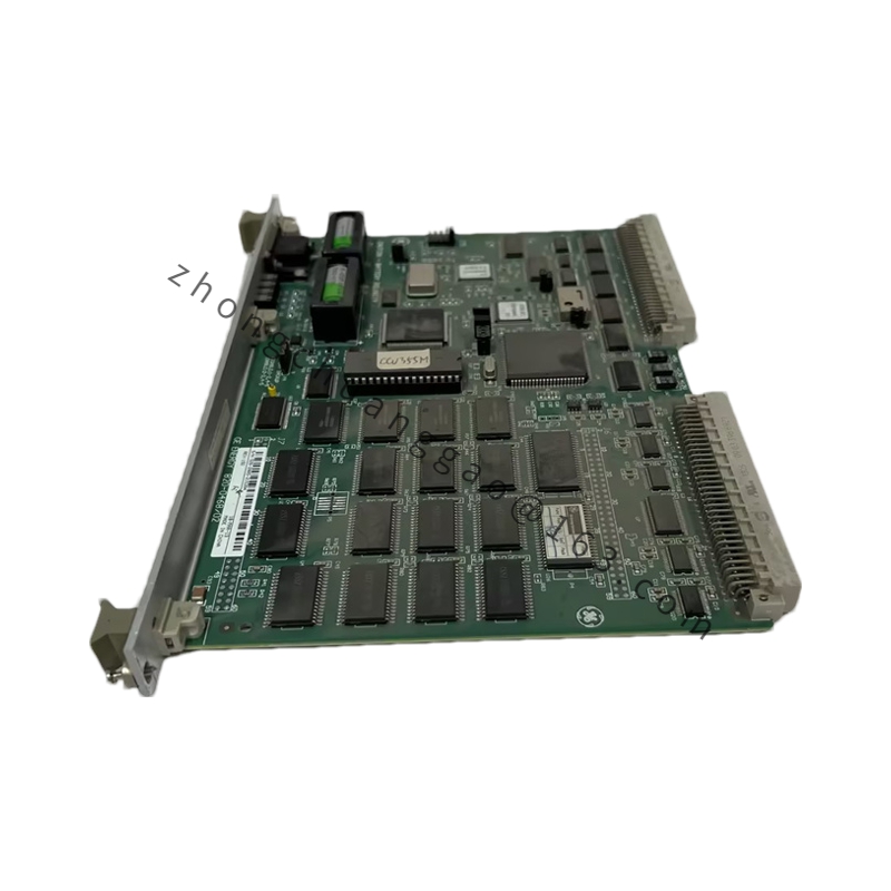
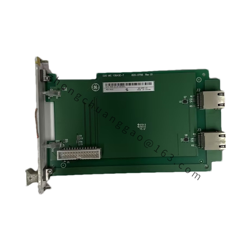
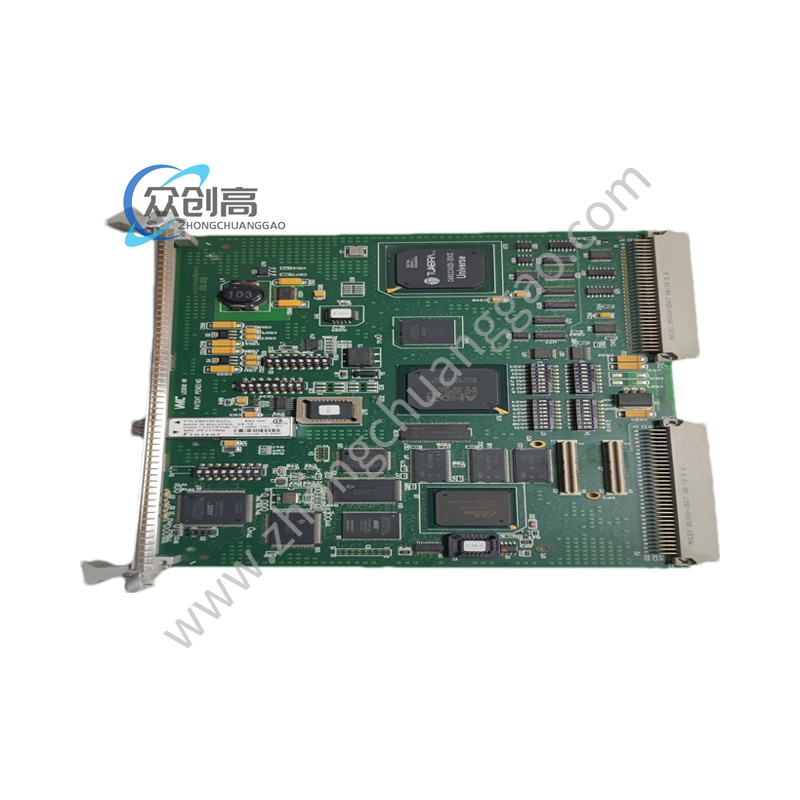
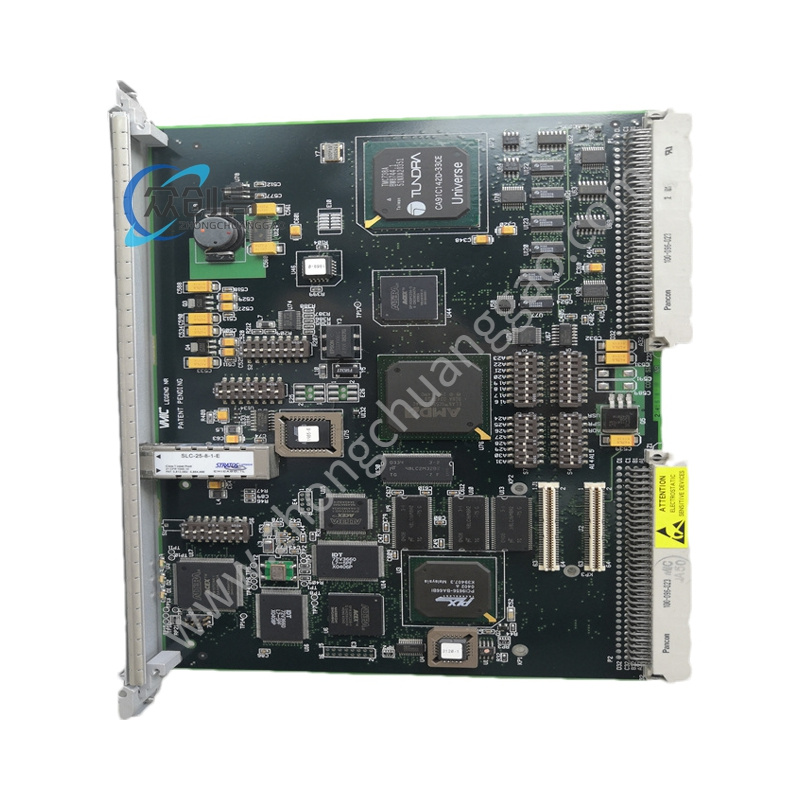
Product Name: GE 531X Series Motor Field Control & Power Supply Board
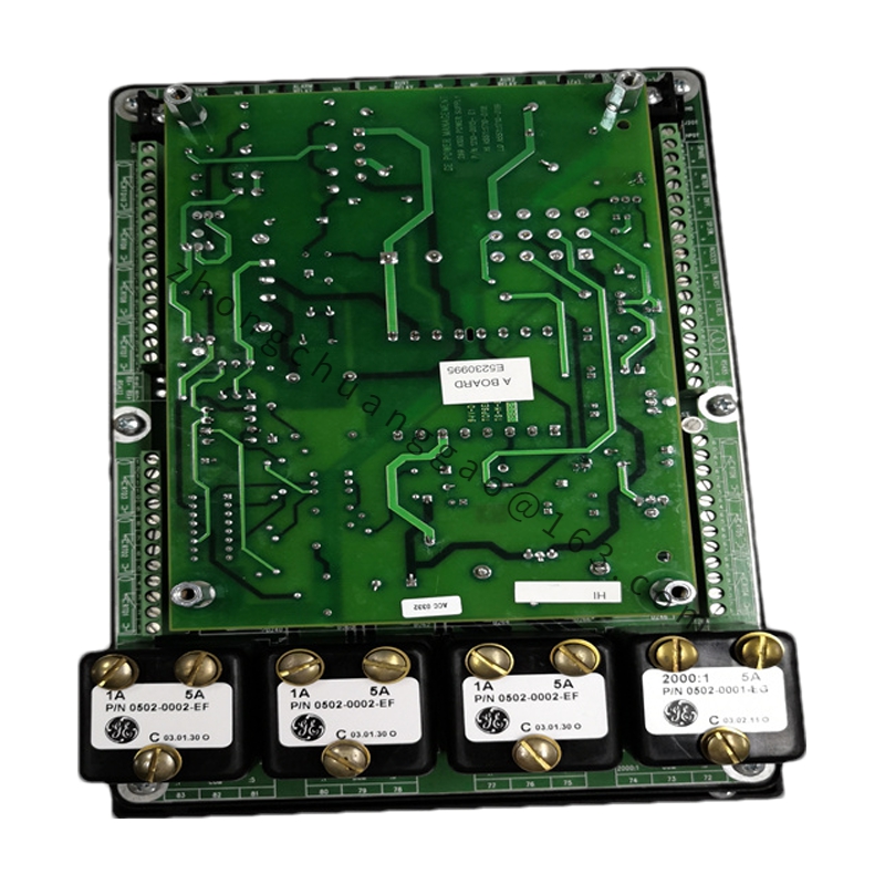
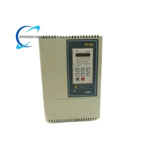
Product Introduction: The GE 531X132APGACG1 is a motor field control and power supply board in GE’s 531X replacement board series, developed for GE drive and exciter systems (including the GE EX2000 excitation system). It provides the necessary power to the drive and powers the motor field (excitation) circuit. The “G3” revision of this board has all MOVs (metal oxide varistors) for the AC line mounted externally rather than on the board.
Detailed content
Technical Specifications:
-
Manufacturer: GE Energy / GE Power Conversion
-
Series: 531X Drive Control Series
-
Board type: Motor field control & power supply board (G3 revision)
-
Power supply outputs: +5 V DC (digital logic, chip power), +15 V DC (analogue signals, op-amp circuits), +24 V DC (relays, terminal circuits, external signals)
-
Motor field excitation: Integrated pulse transformer on board provides drive pulses for the DC motor excitation winding (field circuit)
-
Onboard relays: 3 hardware relay dry contacts — K1 (RUN / driver ready), K2 (MAX / current-speed over-limit alarm), K3 (FAULT / system fault shutdown)
-
Calibration potentiometers: P1 (FIELD SCALE — current feedback range calibration), P2 (CFB ZERO — feedback zero-point offset adjustment), P3 (CFB ADJUST — closed-loop gain fine-tuning)
-
Configurable jumpers: 5 programmable jumpers for configuring feedback signal type and excitation mode
-
Dimensions: 4 cm × 24 cm × 29.2 cm
-
Weight: 0.58 kg
Functional Features:
-
Generates three regulated DC power supplies (+5 V, +15 V, +24 V) for the entire drive controller
-
Provides motor field excitation control via integrated pulse transformer
-
Hardware status feedback through three relays (RUN, MAX, FAULT)
-
Field calibration and adjustment via three onboard potentiometers
-
Configurable feedback and current signals via five jumpers
Working Principle: The board converts incoming AC power into three regulated DC rails (+5 V, +15 V, +24 V) that power the drive controller’s logic, analogue, and relay circuits. Simultaneously, the integrated pulse transformer drives the motor excitation winding, regulating the motor field current. The onboard relays provide hardware-level status and fault signalling; potentiometers and jumpers allow field calibration of the current feedback loop.
Application Scenarios: GE drive systems and exciters, specifically the GE EX2000 excitation system; DC motor drive power and field excitation control.
Installation Requirements:
-
Only trained professionals qualified to handle this type of board shall perform the installation
-
Follow the installation recommendations and wiring diagrams provided by GE in the accompanying manual and data sheet
-
The G3 revision requires externally mounted MOVs connected to the AC line
Usage Precautions:
-
Observe proper handling procedures for static-sensitive electronic assemblies
-
Verify all jumper and potentiometer settings per the application requirement before energising
-
Follow GE’s technical support guidance for first-time installation