Digital guide

You are here:

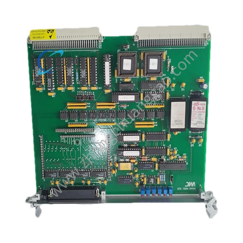
GE 44A398722-G03

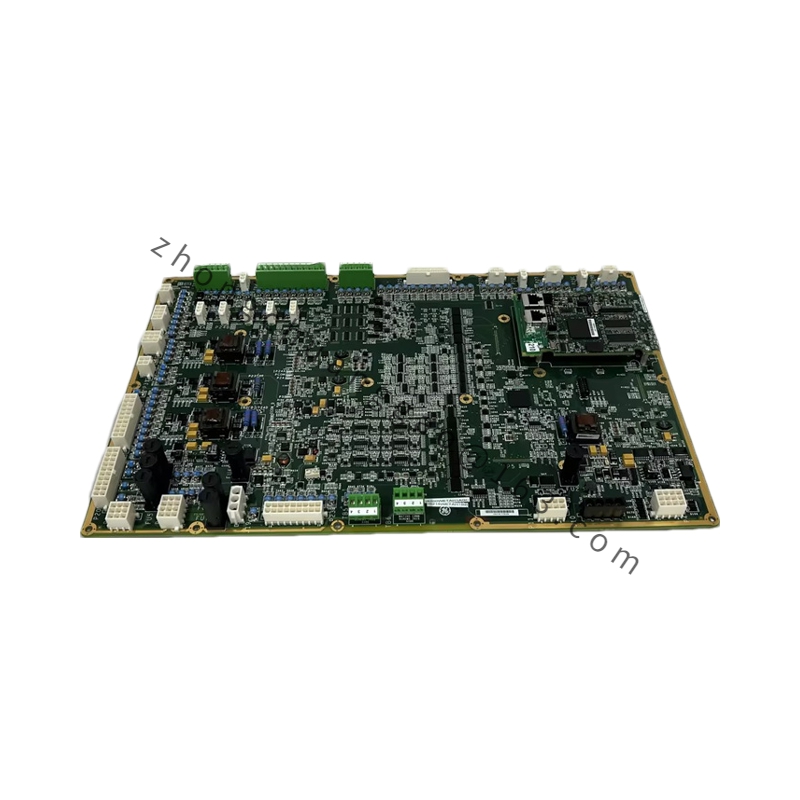
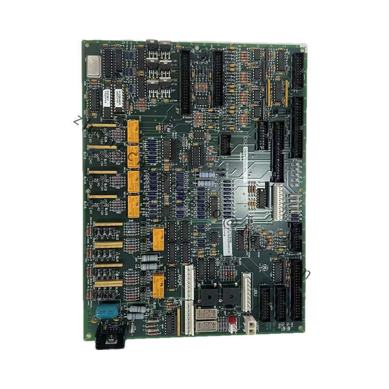
Product Name:​ Multi-channel Digital I/O Module for GE Mark VI / Mark VIe Speedtronic Control System
Product Introduction:​ The 44A398722-G03 is a multi-channel digital input/output module used in GE’s Mark VI / Mark VIe Speedtronic gas turbine control systems. It acquires field discrete signals and issues control commands, serving as a key interface between field devices and the controller.

Detailed content

Technical Specifications:
  • Channel configuration: Multi-channel digital I/O (typically 16 / 32 channels per module definition)
  • Input signal types: Dry contact (passive) / 24 V DC active signal
  • Output signal types: Relay output (dry contact) / transistor output
  • Input voltage range: 12 V DC to 240 V AC (dry contact) / 24 V DC (active)
  • Output contact rating: 5 A @ 250 V AC / 5 A @ 30 V DC
  • Isolation voltage: 500 V DC channel-to-channel, 2500 V DC channel-to-logic
  • Response time: Input filter time selectable (1 ms / 10 ms / 100 ms)
  • Operating temperature: 0°C to +55°C
  • Mounting: DIN rail, 6U VME Eurocard
  • Communication: VME bus / internal I/O bus
  • Power consumption: Typical 5 W, maximum 8 W
Functional Features:
  • Supports mixed dry-contact and active signal inputs
  • Per-channel LED indication showing real-time channel status
  • Software-configurable input filter time to effectively eliminate contact bounce
  • Relay outputs support both AC and DC loads
  • Onboard optocoupler isolation with strong electromagnetic interference immunity
  • Complies with IEC 61000-4 EMC standards
Material Composition:
  • PCB: FR-4 high-Tg (Tg ≥ 170°C) epoxy fiberglass, 6-layer
  • Connector: DIN 41612 Euro-connector (3-row, 96-pin)
  • Relays: OMRON or TE Connectivity industrial relays
  • Optocouplers: Toshiba / Sharp high-speed optocouplers
  • Terminals: Phoenix Contact spring-cage terminals
Structural Characteristics:
  • Standard 6U-height VME Eurocard package
  • Front panel with independent per-channel LED indicators (green = ON, red = OFF)
  • Rear panel: DIN 41612 connector
  • 8-bit DIP switch on top for address setting
  • VME bus guide clips on both sides
Working Principle:​ Field discrete signals pass through input optocoupler isolation and filtering, then convert to digital signals transmitted over the VME bus to the main CPU. Output commands from the CPU drive relay or transistor outputs through the reverse path.
Installation Requirements:​ Install in a 6U VME card cage on DIN rail. Set the address via the 8-bit DIP switch on top. Ensure VME backplane power (+5 V DC) is present. Terminate field wiring on the rear DIN 41612 connector or associated terminal blocks.
Usage Precautions:​ Observe ESD precautions when handling. Do not exceed the stated operating temperature range. Verify correct DIP switch address settings to avoid VME bus conflicts. Respect relay contact ratings (5 A @ 250 V AC / 5 A @ 30 V DC) to prevent premature wear.
You may also like