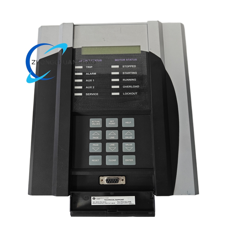
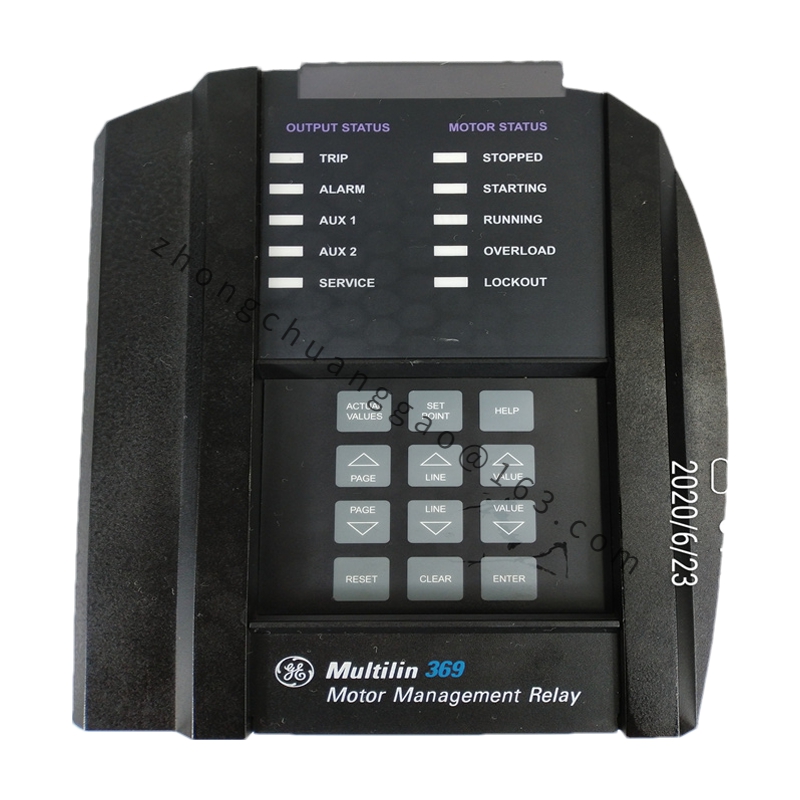
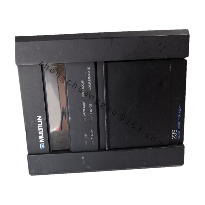
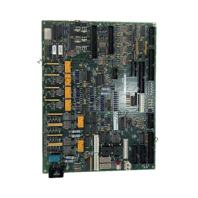
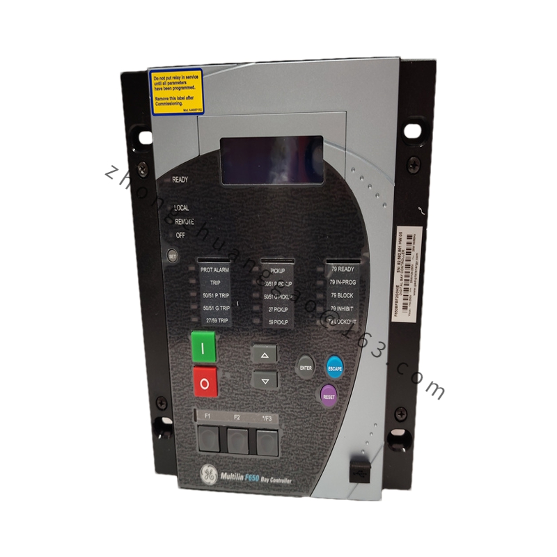
Product Name: GE Multilin 369 Series Motor Management Relay
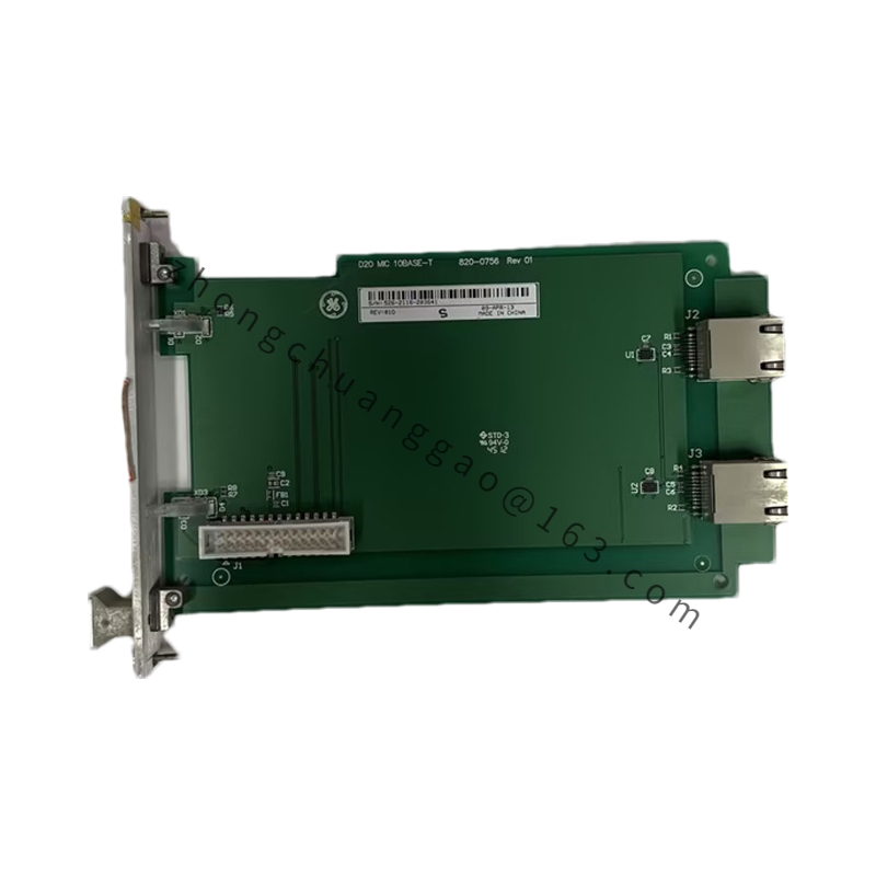
Product Introduction: The 369-HI-0-M-0-D-0-E is a microprocessor-based motor protection relay from the GE Multilin 369 series, designed for comprehensive protection, monitoring, control, and diagnostics of medium and large induction and synchronous motors. The suffix configuration indicates: HI (high-range control power 85–265 VAC / 90–300 VDC), M (Modbus RTU RS-485 + Ethernet 10BaseT communications), and E (50/60 Hz operation).
Digital I/O: Digital inputs, programmable relay outputs
HMI: LED status indicators
Enclosure: Standard panel mount
Operating Temperature: –20 °C to +70 °C (relay variants rated up to –40 °C to +70 °C)
Protection Class: IP40 (front panel)
Protection Functions:
Current protection: Phase overcurrent (instantaneous / definite time / inverse time), ground overcurrent, negative sequence overcurrent (phase loss / imbalance detection), locked rotor protection
Temperature protection: RTD overtemperature with thermal memory and load curve modeling
Voltage protection: Phase overvoltage, undervoltage, voltage imbalance
Other protections: Motor overload thermal simulation (I²t curve), start-up timeout, underload (pump dry-run detection), stall protection
Metering Capabilities: Three-phase current, line voltage, active/reactive power, power factor, energy (kWh), and harmonics up to the 15th order.
Application Scenarios: Pumps, fans, compressors, conveyors, motor control centers (MCC), power generation auxiliaries, oil & gas, mining conveyor networks, and industrial manufacturing pumping systems.
Working Principle: The relay continuously samples CT and RTD inputs, computes thermal models based on I²t curves, and evaluates all protection stages. When a fault or abnormal condition is detected, it operates the appropriate relay output and records event/fault data for diagnostics.
Installation Requirements:
Mount in standard panel cutout with proper sealing for IP40 rating.
Ensure control power wiring matches the HI range (85–265 VAC / 90–300 VDC).
Connect CT secondaries, RTD sensors, and digital I/O according to the 369 series wiring diagram.
Configure IP address, Modbus parameters, and protection settings via EnerVista 369 Setup software.
Usage Notes:
When replacing this exact model, the Ethernet IP configuration is the most frequent “gotcha” — the IP settings must match the plant’s gateway and subnet mask exactly, or the relay will be invisible on the network.
Ensure control power is properly fused at the cabinet level before servicing the HI (high-voltage) variant.
Use an isolated USB-RS-232 dongle when connecting to any RS-232 diagnostic port to avoid grounding issues.