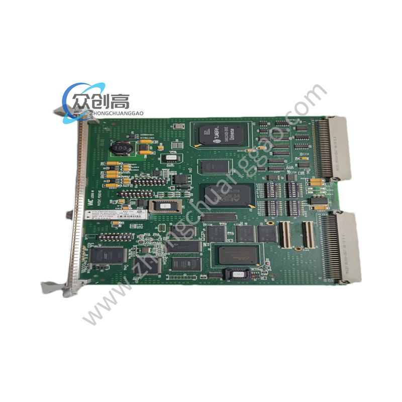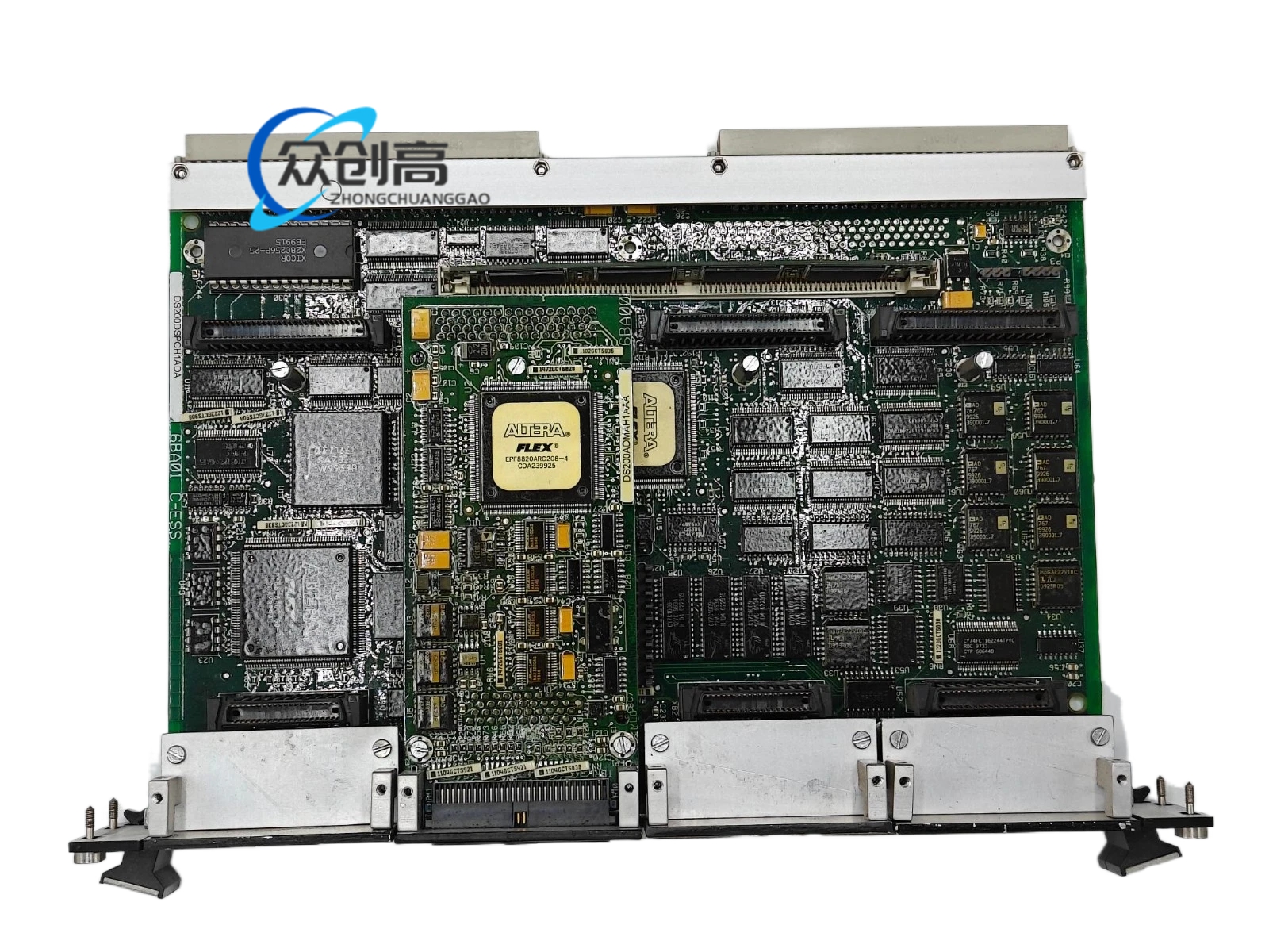

GE 232A4747NCG1A
Product Name: 232A Series Multifunction Motor Protection Relay
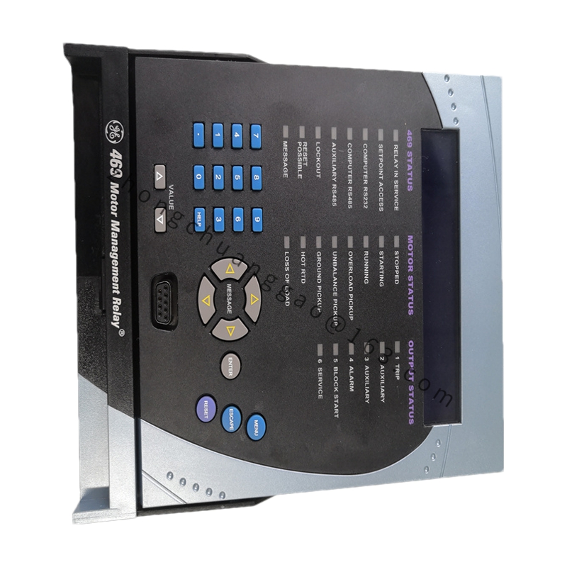
Product Introduction: The 232A4747NCG1A is a digital multifunction motor protection relay in GE’s 232A series, designed for comprehensive protection of medium and low voltage motors. It integrates multiple protection functions including overcurrent, ground fault, overload, undervoltage, overvoltage, phase loss, and locked rotor protection in a single compact device.
Detailed content
Technical Specifications:
-
Manufacturer: General Electric
-
Series: 232A Series / Medium & Low Voltage Motor Protection
-
Rated Current Range: 1 A to 5 A (adjustable)
-
Auxiliary Power: AC/DC 110 V – 240 V or AC/DC 24 V – 125 V
-
Overload Protection (49): 0.4–2.0 × rated current, adjustable
-
Short Circuit Protection (50): 1.5–20 × rated current, adjustable, action time ≤ 0.05 s
-
Ground Fault Protection (51G): 10%–80% of rated current, adjustable
-
Undervoltage Protection (27): 0.5–0.9 × rated voltage, adjustable, delay 0–30 s
-
Overvoltage Protection (59): 1.1–1.3 × rated voltage, adjustable, delay 0–30 s
-
Phase Loss Protection (46): Built-in
-
Locked Rotor Protection (66): Built-in
-
Measurement Accuracy: ±1%
-
Operating Temperature: -20°C to 70°C
-
Mounting: Panel mounting / DIN rail mounting
-
Width: 72 mm (1/8 DIN)
Functional Features:
-
Digital processing with high protection accuracy and fast action speed
-
Built-in Sequence of Events (SOE) recording — stores the last 64 fault events
-
RS485 communication interface for integration with supervisory monitoring systems
-
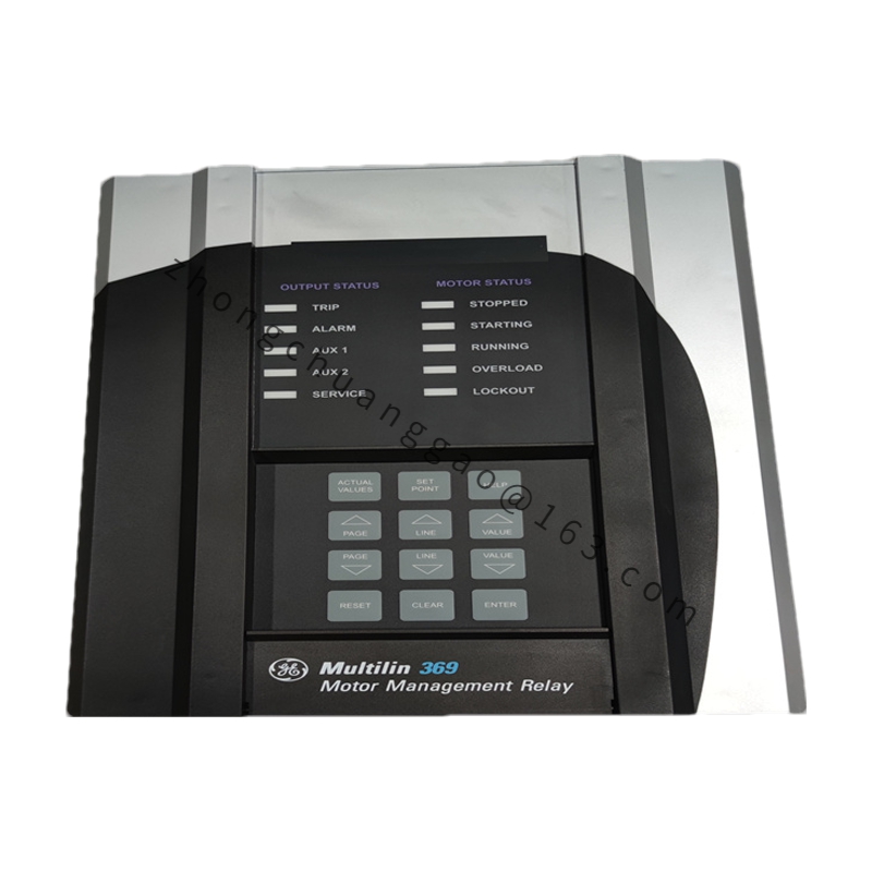
Front panel LED indicators + LCD display for local parameter setting
-
4 programmable output relays
-
Comprehensive motor protection suite (overcurrent, ground fault, overload, undervoltage, overvoltage, phase loss, locked rotor)
Material Composition:
-
Housing: Flame-retardant ABS engineering plastic (UL94 V-0)
-
Front Panel: Polycarbonate (PC) transparent cover
-
Terminals: Nickel-plated copper alloy
Structural Characteristics:
-
Compact panel-mount design, 72 mm width (1/8 DIN)
-
Front panel: LCD display, 4 programming keys, 8 LED indicators
-
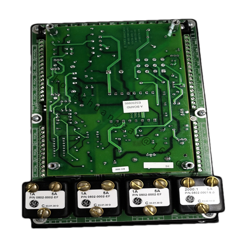
Rear panel: Terminal blocks for current input, voltage input, auxiliary power, and output relays
Working Principle: Current transformers (CTs) connected to the motor supply feed current signals into the relay’s current input terminals; voltage signals are directly connected to the voltage input terminals. The onboard DSP digitizes these signals and continuously evaluates them against the programmed protection curves (overload, short-circuit, ground fault, etc.). When a fault condition is detected, the relay activates the appropriate output relay to trip the motor contactor, and simultaneously records the event in the SOE buffer with a time stamp. The RS485 interface allows the host SCADA system to read measurements, retrieve fault records, and modify protection settings.
Installation Requirements:
-
CT ratio must match the relay’s rated current setting
-
Voltage signals must be directly connected to the relay voltage terminals
-
Mount the relay away from strong electromagnetic interference sources (minimum distance ≥ 100 mm)
-
Select either panel mounting or DIN rail mounting per the cabinet layout
Usage Precautions:
-
CT secondary winding must NEVER be opened while energized — this produces dangerous high voltage
-
After parameter setting, lock the front panel keys to prevent accidental modification
-
Verify the auxiliary power supply range (AC/DC 110–240 V or 24–125 V) matches the available supply
-
Periodically review the SOE record to identify incipient fault patterns