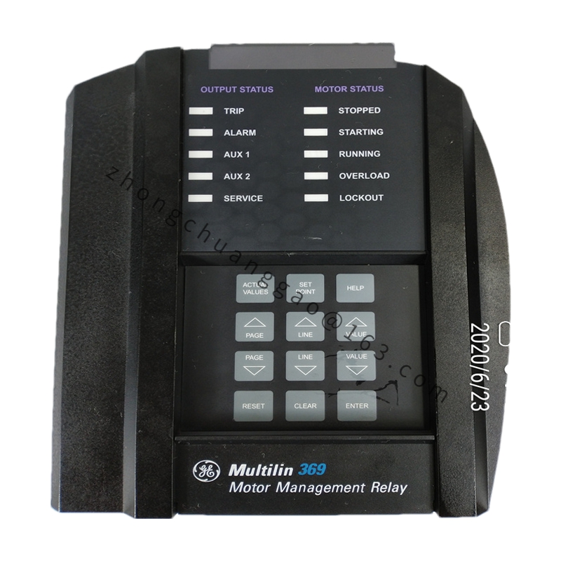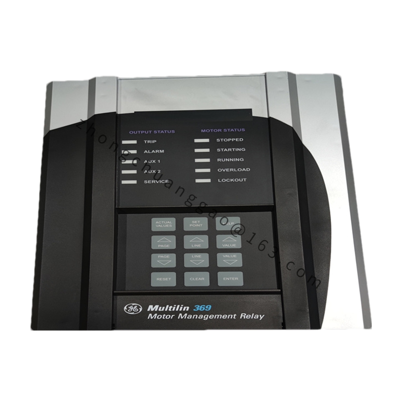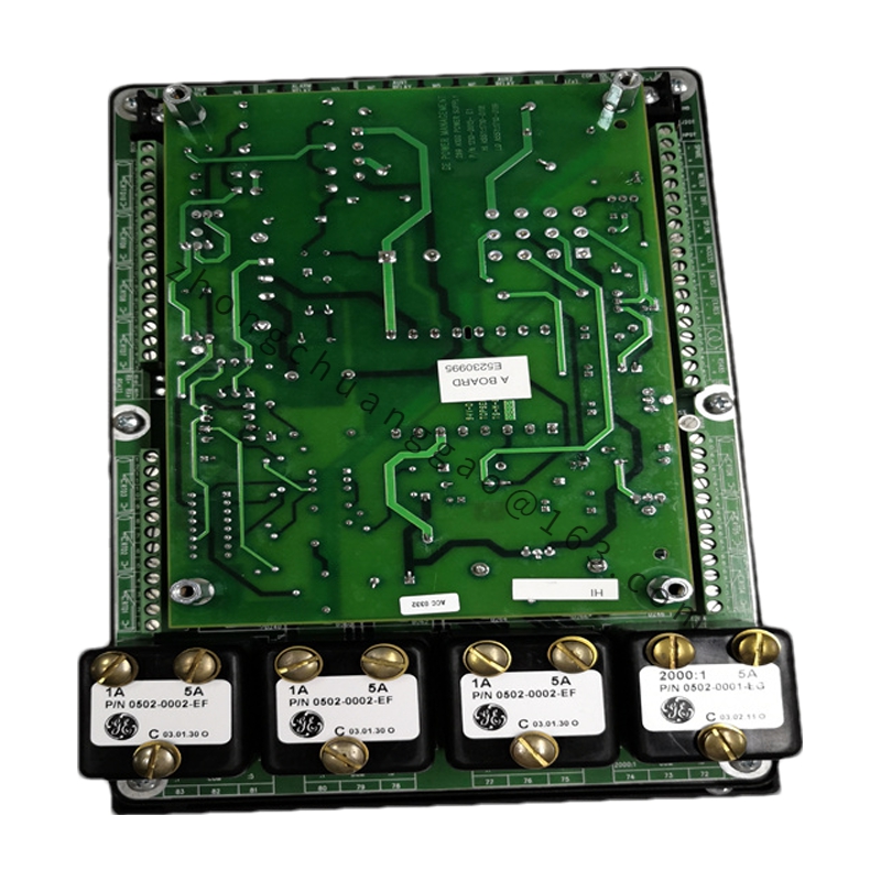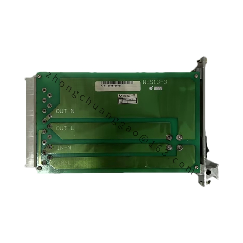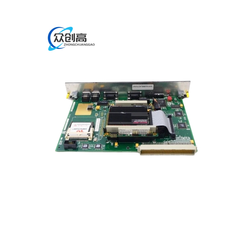
GE 193X-530BB-G01
Product Name: GE Fanuc Output Module (Mark VIe Analog I/O Mixed Module)
Product Introduction: The 193X-530BB-G01 is a GE Fanuc output module and also a Mark VIe distributed control system analog I/O mixed processing module. It integrates both Analog Input (AI) and Analog Output (AO) functions in a single module, acquiring field process variables such as temperature, pressure, flow, and level, and outputting control signals to actuators such as regulating valves. This module effectively saves rack slots and reduces system cost.
Detailed content
Technical Specifications:
-
Manufacturer: GE Fanuc / GE
-
Series: 193X Series / Mark VIe Series I/O Module
-
Analog Input (AI): 8 channels, configurable for 4–20 mA / 0–10 V DC / Thermocouple (TC) / RTD
-
Analog Output (AO): 4 channels, 4–20 mA / 0–10 V DC
-
AI Resolution: 16-bit
-
AO Resolution: 14-bit
-
Thermocouple Types: J, K, T, E, N, S, R, B
-
RTD Types: Pt100, Pt1000, Cu50, Ni120
-
Sampling Cycle: AI ≤ 250 ms, AO ≤ 100 ms
-
Channel-to-Channel Isolation: 250 V DC (between AI and AO)
-
Cold Junction Compensation Accuracy: ±0.5°C (TC channels)
-
Supply Voltage: 5 V DC (backplane power)
-
Operating Temperature: 0°C to +60°C
-
Protection Grade: IP20 (cabinet installation)
Functional Features:
-
AI channels support 4 input types via software configuration (no jumpers required)
-
TC channels have built-in Cold Junction Compensation (CJC), eliminating external compensation modules
-
Signal disconnection detection, over-range detection, and sensor fault detection
-
AO channels support fail-safe output modes (0 mA / 4 mA / hold last value on disconnection, selectable)
-
250 V DC isolation between AI and AO
-
CPU accesses AI/AO data via memory-mapped mode
Material Composition:
-
Housing: Aluminum alloy with black anodized finish
-
PCB: 6-layer industrial-grade components
-
A/D Converter: 16-bit Σ-Δ ADC (e.g., AD7793 or equivalent)
-
D/A Converter: 14-bit DAC + precision V/I conversion circuit (4–20 mA)
-
Terminals: Screw-clamp type, copper alloy with nickel plating
Structural Characteristics:
-
Mark VIe standard I/O module dimensions (single-width installation)
-
Front panel: Per-channel status LEDs (AI: green = normal, yellow = warning, red = fault; AO: green = normal)
-
Rear panel: AI terminal block (8 groups) + AO terminal block (4 groups) + power terminal + backplane connector
-
Secured to rack via locking rail + screws
Working Principle: For AI channels, the field signal (4–20 mA / TC / RTD) passes through a signal conditioning circuit (filtering, amplification, linearization) → A/D conversion → digital value stored in module registers → CPU reads and converts to engineering units. For AO channels, the CPU writes digital values via memory mapping → D/A conversion → V/I conversion → 4–20 mA or 0–10 V DC output to the actuator.
Installation Requirements:
-
Install in Mark VIe standard I/O rack slot
-
Secure module via locking rail + screws
-
Use shielded twisted-pair for AI signals; connect shield to ground at single point (control room end)
-
Backplane 5 V DC supply must be stable before module insertion
Usage Precautions:
-
Do not exceed the 250 V DC isolation rating between AI and AO groups
-
For TC inputs, ensure proper cold junction reference
-
Verify AI channel configuration (current/voltage/TC/RTD) matches the field sensor before energizing
-
AO fail-safe mode must be pre-configured to prevent uncontrolled actuator movement on fault