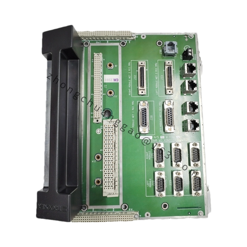
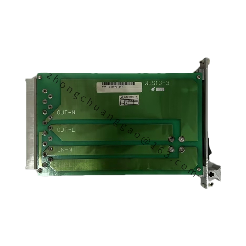
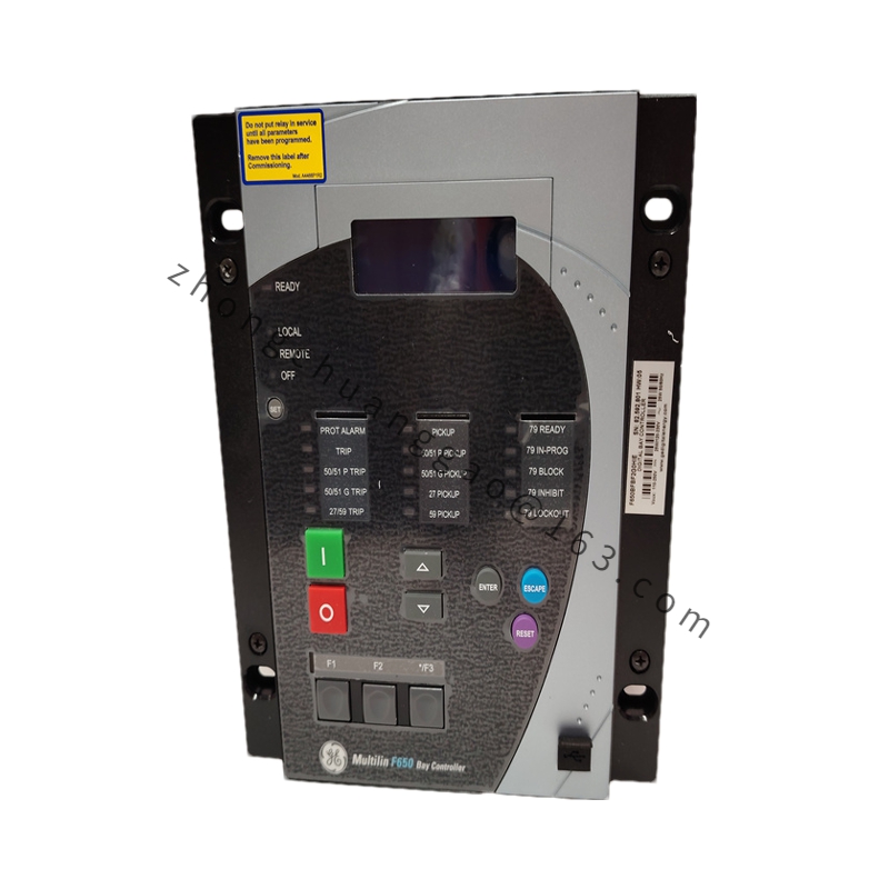
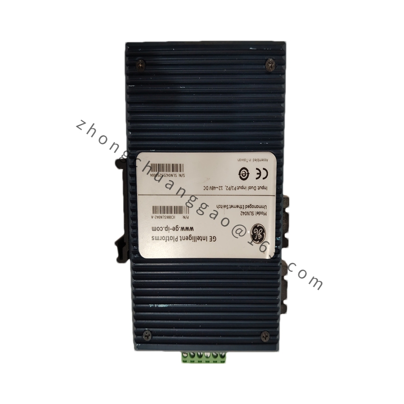
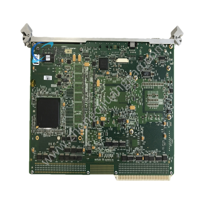
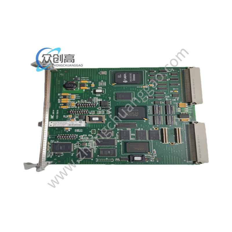
Product Name: Printed Circuit Board (PCB) Module for GE Mark VI / Mark VIe Speedtronic Gas Turbine Control System
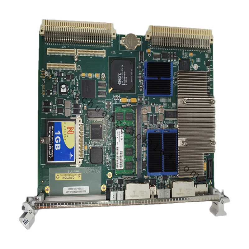
Product Introduction: This module is a dedicated signal-processing PCB used in GE’s Mark VI / Mark VIe Speedtronic gas turbine control platforms. It performs analog input/output and signal conditioning duties as a core interface component of the turbine control system.
Connector: DIN 41612 Euro-connector (3-row, 96-pin)
Key ICs: Analog Devices high-precision ADC / DAC chips
Capacitors: Tantalum and ceramic capacitors in hybrid configuration
Structural Characteristics:
Standard 6U-height VME Eurocard package
Front panel equipped with LED status indicators (Run / Fault / Comms)
Rear panel: 3-row 96-pin DIN 41612 connector
Onboard jumpers for address setting and function configuration
Card guide slots on both sides for rail fixation
Working Principle: External sensor signals pass through signal conditioning circuits (filtering, amplification, isolation) and enter the high-precision A/D converter. Digital signals are transmitted via the VME bus to the main CPU for computation. Control outputs are driven to actuators after D/A conversion, realizing precise control of the gas turbine.
Installation Requirements: Install into a standard 6U VME card cage. Ensure the DIN 41612 connector is fully seated. Verify +5 V DC and ±15 V DC power rails are present before power-up. Use proper ESD handling procedures when inserting or removing the board.
Usage Precautions: Observe ESD precautions at all times when handling. Do not exceed the stated operating temperature range. Confirm correct board address jumper settings before system power-up to avoid VME bus conflicts.