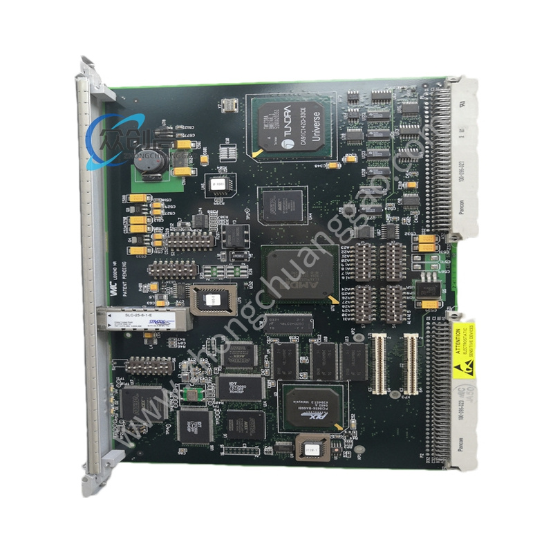
GE 173C8413BAG02
Product Name: GE 173C Series 2100V 4-Quadrant SCR Stack (Power Semiconductor Stack)
Product Introduction: The 173C8413BAG02 is a GE 173C series power semiconductor stack, specifically a 53 mm 2100 V 4-quadrant (4Q) SCR stack assembly. It belongs to GE’s extensive line of 173C power modules used in large motor drives, excitation systems, and high-power converter applications.
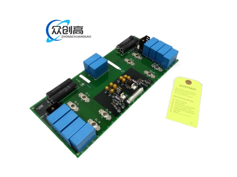
Detailed content
Technical Specifications:
-
Manufacturer: General Electric
-
Series: 173C
-
Model: 173C8413BAG02
-
Stack Thickness: 53 mm
-
Voltage Rating: 2100 V
-
Topology: 4-Quadrant (4Q) SCR Stack
-
Related variants in the 173C family range include:
-
173C8413BAG01: STACK 53MM 1400V 4Q
-
173C8413BAG02: STACK 53MM 2100V 4Q
-
173C8413BBG02: STACK 53MM 2100V 1Q
-
173C8413BCG01: SCR CELL ASSM 77MM
-
173C8413BDG02: STACK 77MM 3000V 1Q
-
Functional Features:
-
4-quadrant operation enabling bidirectional power flow (motor drive and regenerative braking)
-
High-voltage 2100 V rating for medium-voltage converter applications
-
53 mm stack thickness standard form factor
-
Integrates multiple SCR cells in a controlled assembly for high-power switching
Material Composition:
-
SCR semiconductor chips (silicon controlled rectifiers)
-
Copper-based heat conduction elements
-
Insulating layers (ceramic/alumina) for electrical isolation
-
Mechanical compression frame (spring-loaded or bolted stack)
Structural Characteristics:
-
53 mm thick stack assembly
-
Compression-bonded SCR cells with interleaved heat sinks
-
High-voltage isolation barriers between conducting layers
-
Designed for bolt-down or clamp-in mounting in drive cabinets
Working Principle: The SCR stack functions as a high-power controlled rectifier bridge. By gating the individual SCR cells in the appropriate sequence, the 4-quadrant topology allows current to flow in both directions and voltage polarity to be reversed, enabling both motoring and regenerating operation. Gate pulses from the drive controller trigger each SCR at the precise firing angle to produce the desired output voltage and current waveform.
Installation Requirements:
-
Mount in the designated drive cabinet location with adequate heat sink contact
-
Apply correct torque to the compression bolts per GE 173C series specification
-
Ensure the cooling system (air or liquid) is operational before energizing
-
Verify the 2100 V isolation clearances are maintained to adjacent conductors
Usage Precautions:
-
Never exceed the 2100 V rating; observe proper snubber circuits to limit dv/dt
-
Monitor junction temperature via the drive system; do not exceed the SCR cell thermal limits
-
When replacing the stack, verify the exact 173C8413BAG02 part number — the 1Q variants (e.g., 173C8413BBG02) are NOT interchangeable for 4Q applications
-
De-energize and wait for full discharge of all capacitive elements before handling