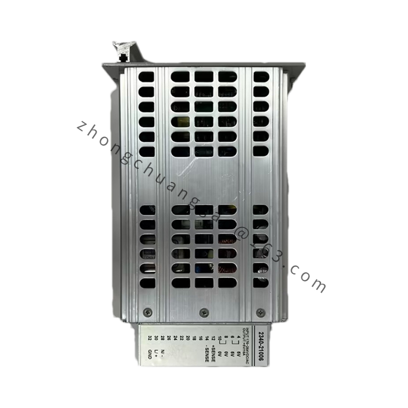
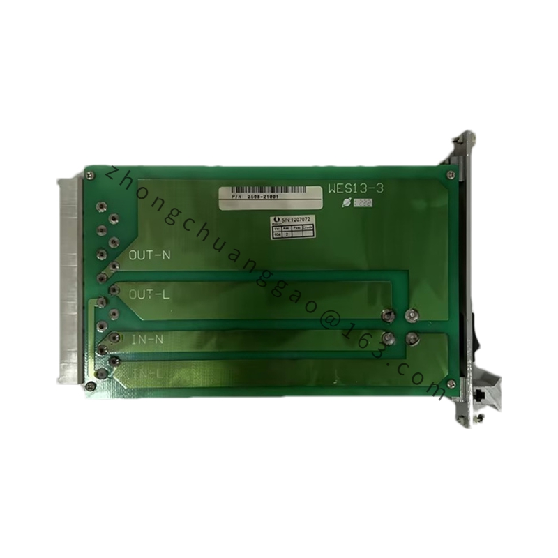
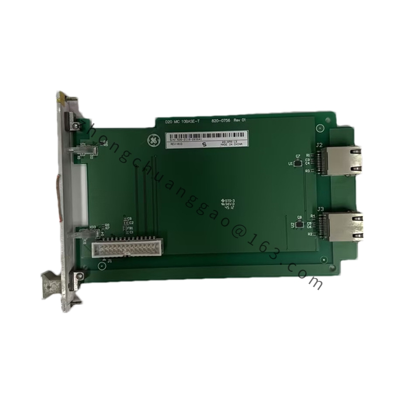
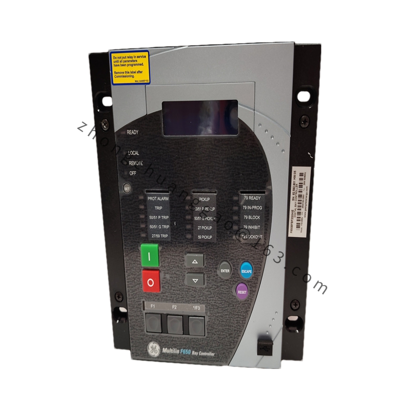
Product Name: GE Mark V/VI Analog Input Module (AI)
Product Introduction: An analog input board for GE Mark V and Mark VI Distributed Control Systems (DCS), used to acquire field analog signals (such as 4–20 mA and 0–10 V) and convert them into digital values for processing by the main controller.
Technical Specifications:
Module Type: 8-channel analog input (configuration-dependent)
Channel Isolation: Inter-channel isolated, 250 V DC isolation voltage
Power Supply: +5 V DC (via backplane bus)
Communication: Backplane bus (VME-style)
Operating Temperature: 0 °C to +60 °C
Storage Temperature: –40 °C to +85 °C
Humidity: 5 % to 95 % non-condensing
Vibration Resistance: 5 g, 10–500 Hz
Power Consumption: ≤ 1.5 W (typical)
CMRR: ≥ 90 dB @ 50 Hz
Material & Construction:
PCB: FR-4 multi-layer surface-mount board
Connectors: Gold-plated spring contacts
Housing: Metal shielded enclosure
A/D Converter: High-precision Σ-Δ ADC
Form Factor: Standard PCB card, approx. 165 mm height, 64-pin backplane connector on top, analog input terminal blocks on bottom, channel status LEDs on front
Functional Features: 8 independent AI channels with per-channel signal type configuration; software calibration with field-adjustable zero and span; wire-break detection; cold-junction compensation (for thermocouple input when paired with dedicated modules); onboard watchdog timer with automatic timeout reset.
Working Principle: Field 4–20 mA or 0–10 V signals enter via the bottom terminals, pass through signal conditioning circuitry (filtering and amplification), then are digitized by the 13-bit Σ-Δ ADC. Results are transferred over the backplane bus to the PLC/DCS CPU for PID computation or data display.
Application Scenarios: Process control, thermal power generation, petrochemical plants, gas turbine monitoring.
Installation Requirements: Plug-in backplane mounting. Ensure backplane supplies correct +5 V DC. Verify signal wiring matches configured input type per channel.
Usage Notes: Perform regular calibration checks. Confirm wire-break detection logic is mapped correctly in the control program. Maintain ambient temperature within specified range.