GE 137D6723G1
Product Name: GE 137D6723G1 Multifunction Overcurrent Protection Relay
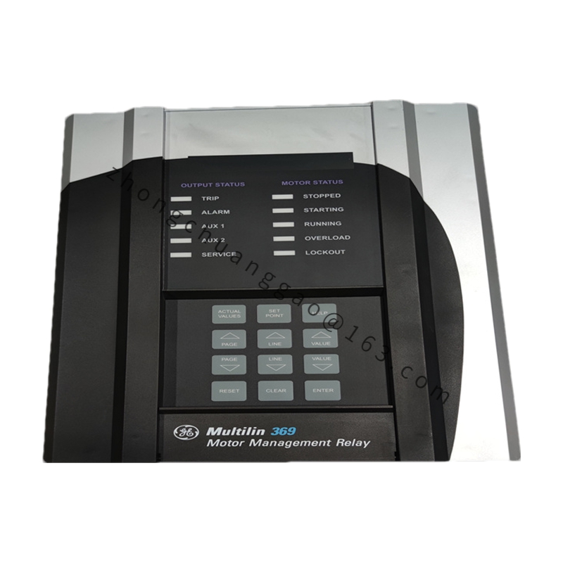
Product Introduction: The GE 137D6723G1 is a multifunction digital overcurrent protection relay. It integrates 50/51 overcurrent protection, 50G/51G residual overcurrent protection, 27 over/undervoltage protection, and 81O/81U over/underfrequency protection in a single 1/4 DIN panel-mount device. It is used for the protection of medium/high-voltage distribution systems and industrial motors.
Detailed content
Technical Specifications:
-
Protection functions: 50/51 overcurrent, 50G/51G residual overcurrent, 27 over/undervoltage, 81O overfrequency, 81U underfrequency
-
Rated current: 5 A or 1 A (configurable)
-
Current input range: 0.1–120 A (secondary)
-
Voltage input range: 19–347 V AC/DC
-
Accuracy: Current measurement ±0.5%
-
Time delay range: 0–60 seconds (programmable)
-
Communication interface: RS-485 / Modbus RTU
-
Operating power: 48–250 V AC/DC, 50/60 Hz
-
Operating temperature: -20 °C to +70 °C
-
Protection rating: IP51 (front panel)
-
Display: 4-digit LED front panel showing real-time current values
-
Dimensions: 96 mm × 96 mm (1/4 DIN)
-
Panel cut-out: 92 mm × 92 mm
-
Measurement: Three-phase current + residual current with imbalance detection
-
Fault recording: Last 4 fault waveforms
-
Event recording (SOE): Time resolution ≤ 1 ms
Functional Features:
-
Multifunction integration — one relay replaces multiple traditional relays
-
Programmable curve characteristics: standard inverse, very inverse, definite time
-
Built-in fault waveform recording for post-event analysis
-
Remote reset and remote programming support
-
High-accuracy measurement: ±0.5% current accuracy meeting metering-class requirements
-
Wide voltage input range: 48–250 V AC/DC universal
-
Four-digit LED front-panel display for real-time current indication
Material Composition:
-
Enclosure: Polycarbonate (PC) engineering plastic, flame-retardant rating UL 94 V-0
-
Front panel: UV-resistant transparent acrylic cover
-
Terminals: Nickel-plated copper alloy, corrosion-resistant
Structural Features:
-
1/4 DIN panel-mount construction, 96 mm × 96 mm
-
Bottom wiring terminal block with screw-clamp connections
-
Rear RS-485 communication terminals and auxiliary relay output terminals
Working Principle: The relay acquires three-phase and residual currents via built-in current transformers (CTs). A 16-bit A/D converter samples the signals, and a DSP processor continuously executes the user-programmed protection curves. When a measured value exceeds the set threshold for longer than the programmed delay, the relay actuates its internal output relay to issue a trip signal. Fault information is simultaneously uploaded to the host SCADA system via RS-485.
Application Scenarios: Medium/high-voltage distribution systems (11 kV / 33 kV / 66 kV), industrial motor protection, petrochemical plant distribution, mining power supply systems, rail transit power supply.
Installation Requirements:
-
Mount in a standard relay cabinet / switchgear panel; panel cut-out 92 mm × 92 mm
-
CT secondary circuits must be reliably grounded (grounding resistance ≤ 4 Ω)
-
Auxiliary power wiring must distinguish L/N polarity to prevent reverse connection
-
Communication cabling shall use shielded twisted pair; maximum communication distance 1200 m
Usage Precautions:
-
CT ratio must be accurately configured in the relay settings, otherwise protection pick-up values will be incorrect
-
Never connect voltage signals to current input terminals
-
Verify all wiring is tight and secure before energising the relay
-
Recommended calibration interval: once every 2 years to ensure protection accuracy