GE 107W7460P001
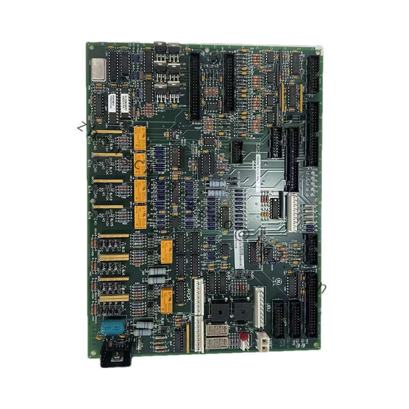
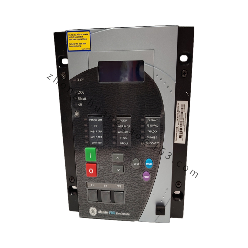
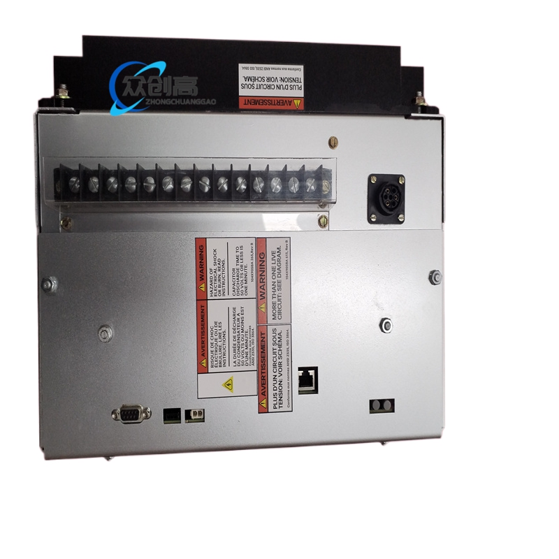
Product Introduction (Relay Interpretation): The 107W7460P001 is a static overcurrent relay produced by General Electric, belonging to the 107W product series. It is used for overcurrent protection of generators, transformers, and feeder circuits, supporting both instantaneous and time-delayed overcurrent protection functions.
Technical Specifications (Relay Interpretation):
- Series: 107W
Detailed content
- Specification Code: 7460
- Configuration Code: P001
- Rated CT Secondary Input: 5 A
- Overcurrent Setting Range: 1.5–15 A (based on 5 A reference)
- Instantaneous Overcurrent Trip Time: ≤ 25 ms
- Definite-Time Overcurrent Delay Range: 0–30 s (adjustable)
- Auxiliary Power: 125 VDC / 250 VDC (depending on configuration)
- Output: 1 × SPDT relay output
- Accuracy: ±2.5%
Functional Characteristics (Relay Interpretation):

- Function 50 — Instantaneous overcurrent: High-speed tripping for severe short-circuit faults
- Function 51 — Definite-time overcurrent: Adjustable time-delayed overcurrent protection for backup protection
- Static design: No mechanical moving parts, excellent anti-vibration performance
- Panel setting: Parameter adjustment via front-panel knobs, no special tools required
- Power-loss memory: Settings retained during power interruption
Structural Features (Relay Interpretation):

- Modular plug-in design
- Front panel with setting knobs and LED indicators
- Standard 1/4 DIN size enclosure
Application Scenarios (Relay Interpretation): Power plants, substation feeder protection, industrial power distribution systems, marine power systems.
Alternative Identification (IGBT Module Interpretation): Per ConverterTec’s multi-brand cross-reference, 107W7460P001 is the GE equivalent part number for the I-07460 IGBT – Line Side Non-ESS module in GE 1.X wind turbines. In this context, it is a phase module in GE’s 1.X converter, available as a retrofit IGBT module solution for improved performance and extended converter lifetime.
Installation Requirements (Relay Interpretation):
- Verify CT secondary circuit integrity and correct ratio before installation.
- Ensure auxiliary power matches the configured voltage (125 VDC or 250 VDC).
- Adjust overcurrent pickup and time-dial settings per protection coordination study.
- Properly terminate the SPDT relay output contact in the trip circuit.
Usage Notes:
- Given the conflicting documentation, verify the exact application (protection relay vs. wind turbine converter IGBT module) with the equipment manufacturer or the original panel/system documentation before ordering or installing.
- As a relay: when used in a 5 A CT secondary circuit, never open the CT secondary while the relay is connected, as this produces dangerous high voltages.