Technical Specifications
Input voltage: 24 VAC (±10%/−15%) 50/60 Hz or 24 VDC (±10%); 19-inch rack adapters are also available with 120 VAC or 220 VAC primary power.
Scanner inputs: two independent channels A and B.
Dynamic range: 1900 pulses per second.
Flame failure response time: 1 s to 6 s adjustable.
Relays: one fused DPDT flame relay, one SPDT marginal alarm relay.
Analog output: 4 mA to 20 mA flame signal, scalable.
Display: 8-character alphanumeric LED.
Communications: Modbus and Allen-Bradley DF1 to PLC.
Operating temperature: -20°C to 60°C.
Rack format: 19-inch, approximately 1.98 in wide, 5.06 in high, 7.0 in deep.
Compatible scanners: 45UV5, 45RM1/2/4, 45FS1 and related Fireye pulse scanners.
Functional Features
Dual-scanner pulse analysis with independent threshold settings.
Password-protected keypad configuration.
Adjustable pull-in/drop-out and delay-on timers.
Scanner Option 1 / Option 2 logic selected by external dry contact.
Remote flame signal reporting via 4-20 mA and digital protocol.
Material Composition and Structure
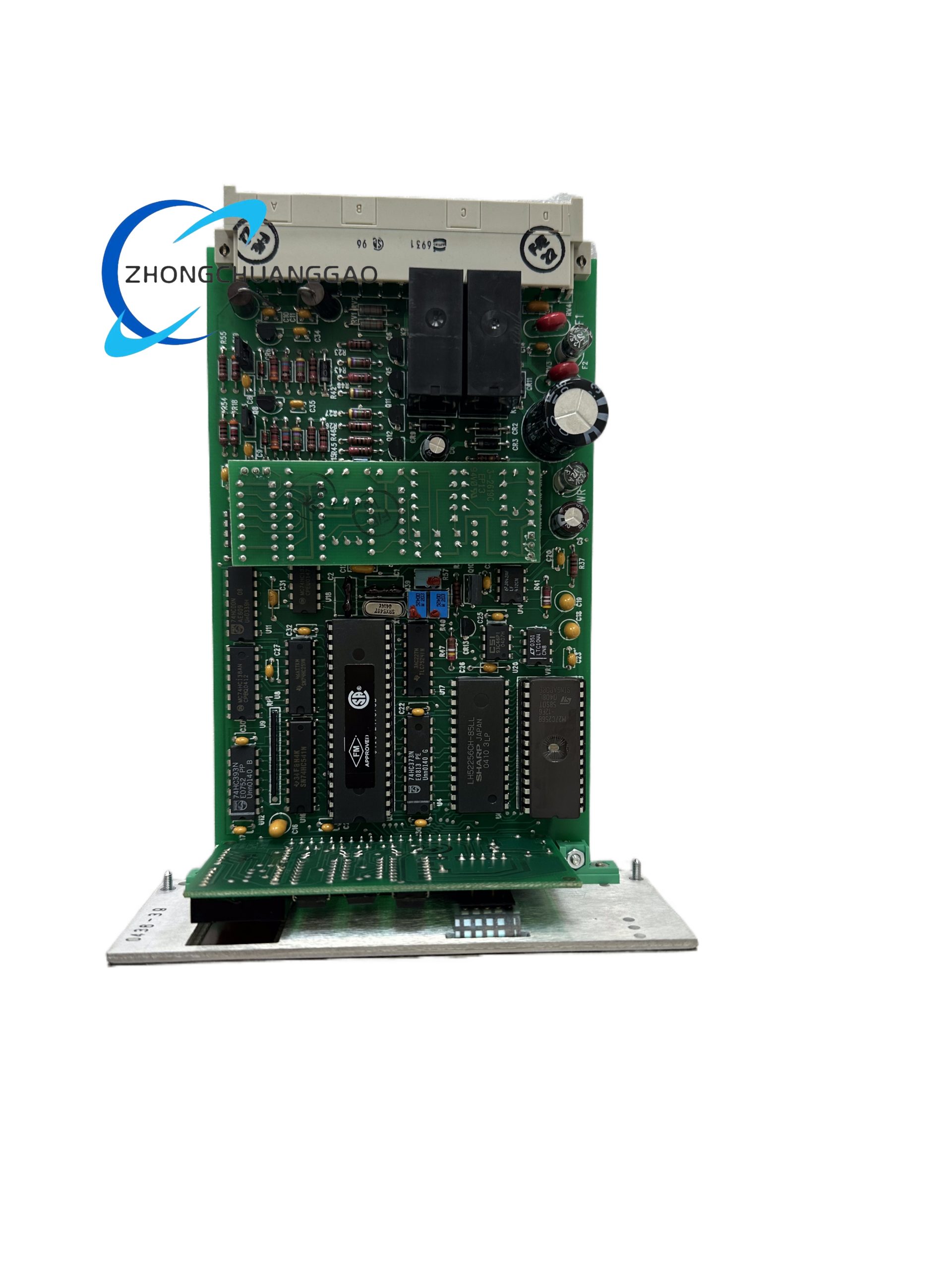
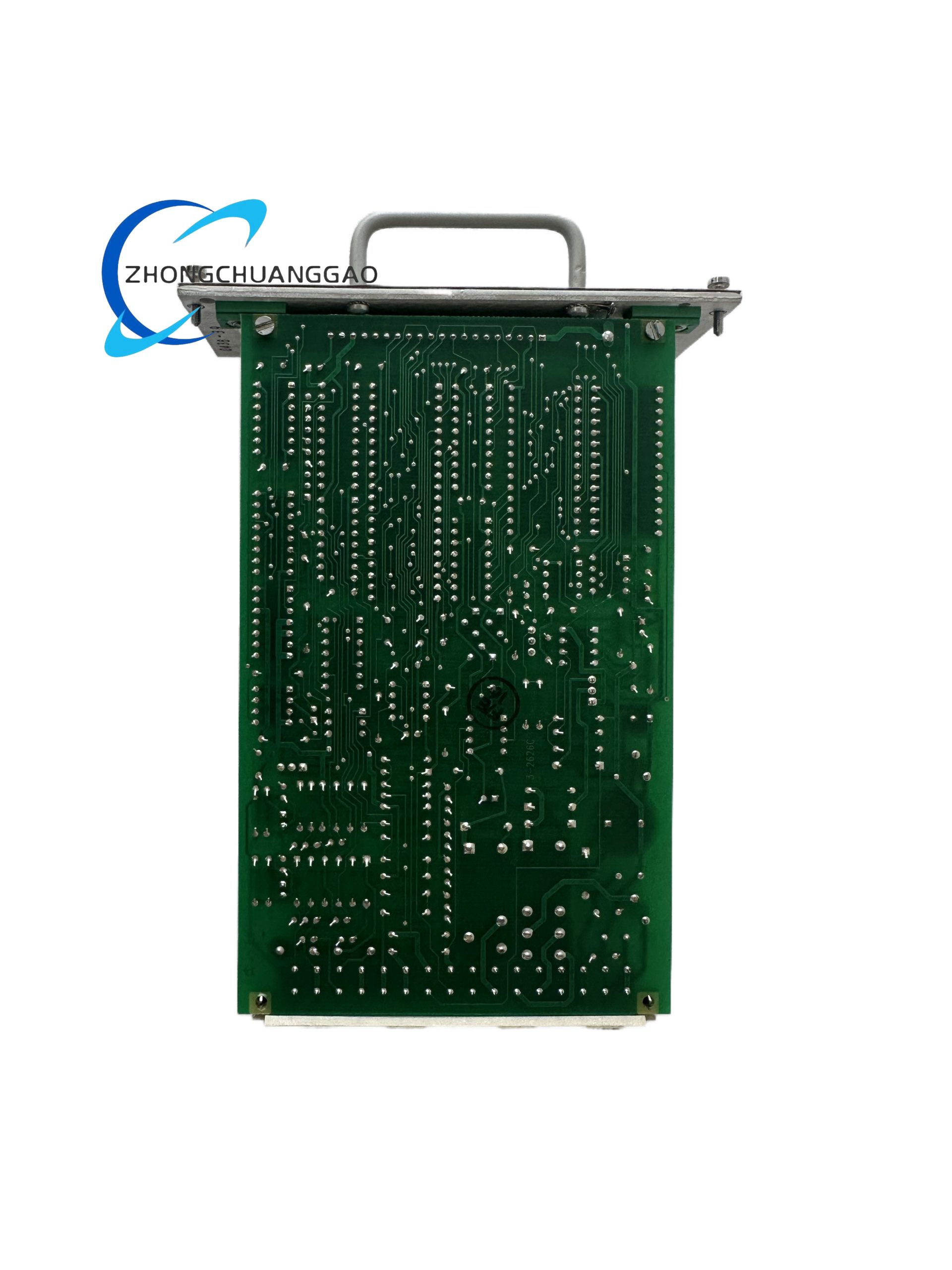
19-inch rack amplifier board in molded front-panel bezel, electronic control PCB, power supply section, relay outputs, DPDT/SPDT contacts, alphanumeric display, and rear scanner/communication connectors.
Working Principle
Scanner pulses are conditioned and counted. The microprocessor compares pulse rate and amplitude against programmed flame thresholds. If valid flame is confirmed, the DPDT flame relay energizes; loss or irregular pulse pattern initiates failure response within the adjusted FFRT.
Installation Requirements
Mount in 19-inch rack, half-rack, or surface rack per Fireye 60-2471/60-2530 families. Use shielded scanner cables. Connect 24 VAC/DC or rack adapter AC supply. Ground signal shields at the amplifier end. Configure scanner option and thresholds before burner light-off.
Usage Notes
Verify scanner compatibility before wiring. Test flame relay and 4-20 mA output during commissioning. Keep FFRT consistent with burner management system approvals. Perform periodic pulse-rate verification for each scanner.