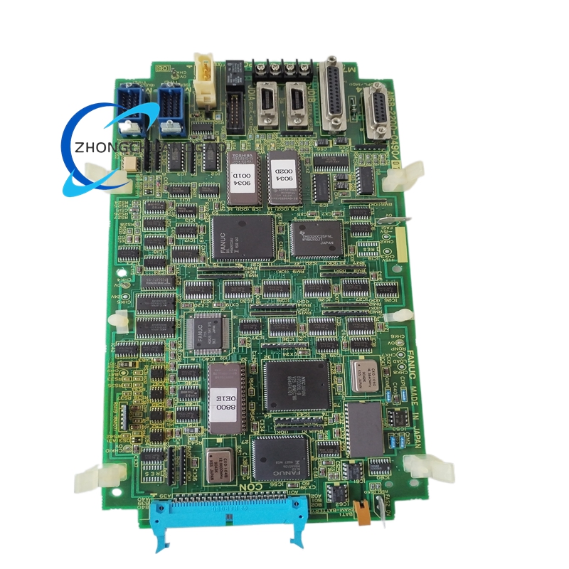
FANUC A16B-2200-0490
Product Name
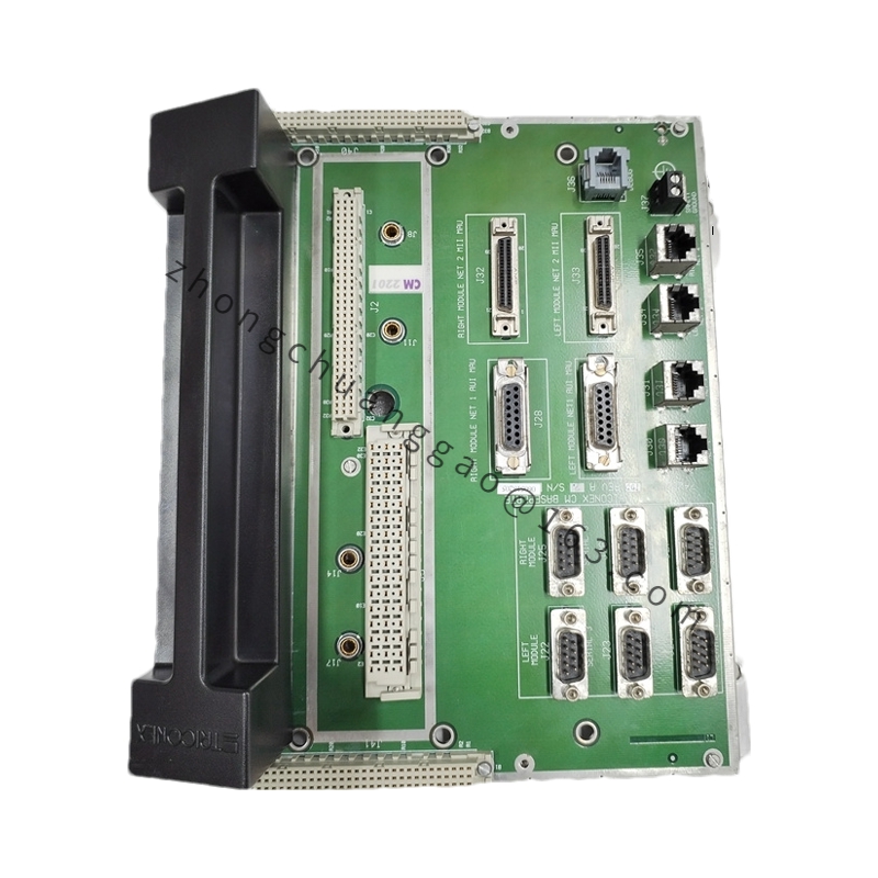
PowerMate A series base board / system backplane board.
Product Introduction
This board serves as the base printed circuit assembly for Fanuc PowerMate A and related small CNC configurations. It distributes power, provides card slots, and carries internal bus connections between CPU, axis control, I/O, memory, and peripheral boards.
Detailed content
Technical Specifications
Board type: CNC base board / backplane board.
System compatibility: Fanuc PowerMate A series; supplier listings also reference Series 16 base applications.
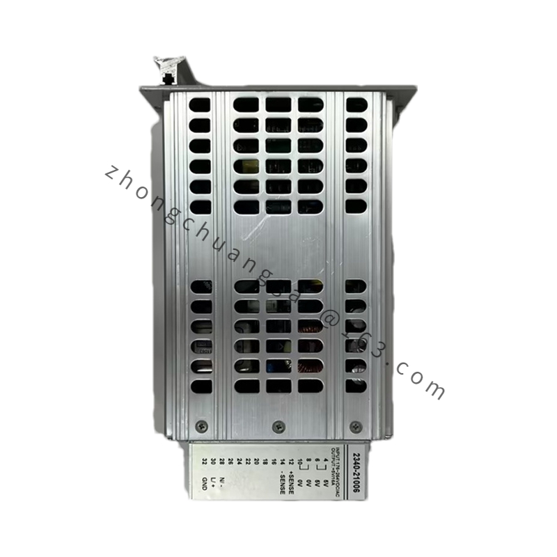
Power supply: internal DC 5 V and plus/minus 15 V distribution; some multilayer control board descriptions list DC 24 V logic or I/O support according to build.
Bus interface: internal CNC backplane bus.
Communication: RS232C and high speed serial options according to installed subboards.
I/O capacity: up to 32 digital I/O points in listed PowerMate base configurations.
Operating temperature: 0 to 55 °C.
Storage temperature: -20 to 70 °C.
Humidity: non condensing industrial cabinet limits.
Weight: approximately 0.28 to 0.5 kg according to board version and fitted hardware.
Functional Features
Distributes DC power to plugged controller cards.
Provides backplane data and address bus connections.
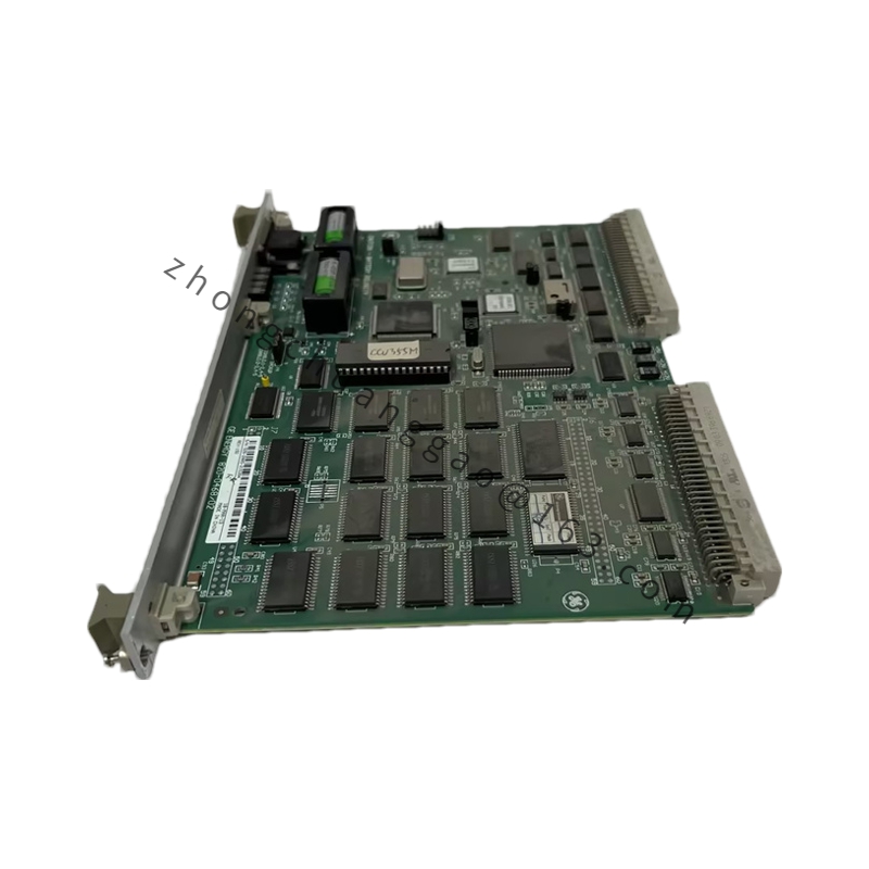
Houses CPU, axis, I/O, memory, and interface card slots.
Supports RS232 and serial communication subboards.
Centralizes system diagnostics through connected controller cards.
Application Scenarios
PowerMate A small CNC retrofit and maintenance.
Legacy Fanuc Series 16 base board service where form factor matches.
Standalone lathe or milling control base hardware.
Teaching, repair, and spare parts inventory for obsolete CNC cabinets.
Performance Parameters
Backplane bus transfer governed by installed CPU and subboard firmware.
Digital I/O scanning according to CNC ladder and parameter configuration.
Stable 5 V and plus/minus 15 V distribution for logic and analog sections.
Operating envelope 0 to 55 °C inside a controlled cabinet.
Material And Construction
Multilayer FR4 printed circuit substrate where used as control board version.
Gold plated edge connectors and socket contacts.
Backplane slots for CPU, axis, I/O, and memory subboards.
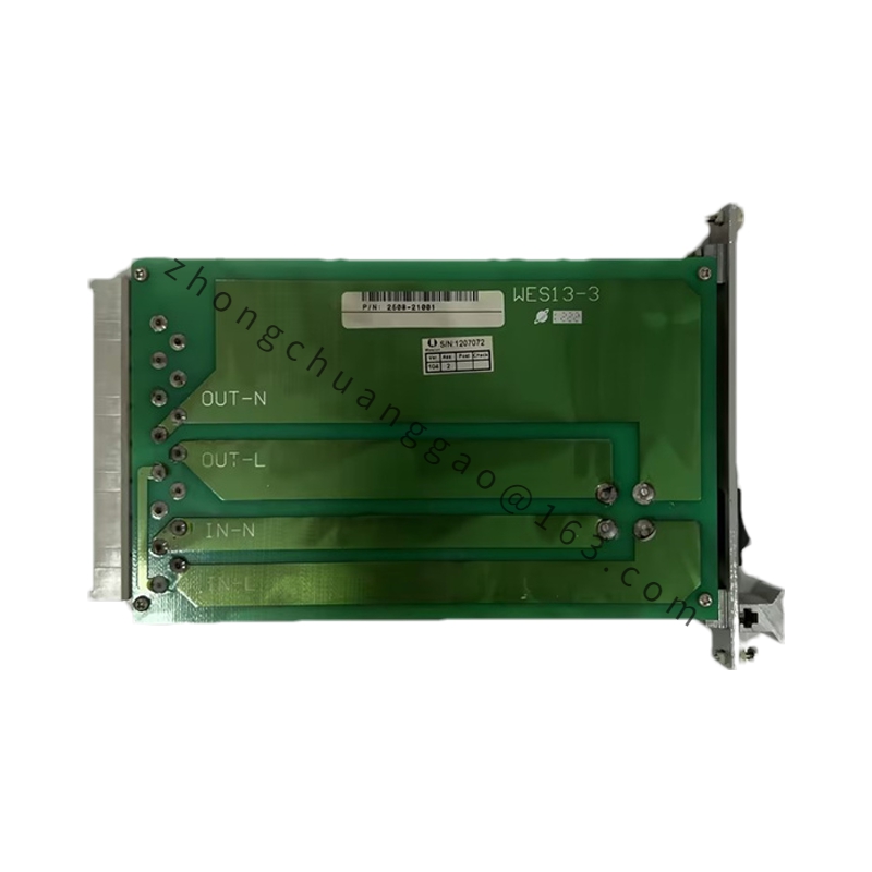
Power distribution tracks, bus drivers, and termination components.
Chassis fixing holes and cabinet mounting hardware.
Working Principle
The base board receives internal DC supplies and distributes them to each plugged card. The backplane bus transfers address, data, control, and interrupt signals between CPU, axis control, I/O, and memory boards. External servo, operator panel, and sensor signals reach the system through connected subboards and backplane routing.
Installation Requirements
Install in the designated PowerMate A or matched system chassis.
Seat every subboard fully into its assigned slot.
Verify DC 5 V, plus/minus 15 V, and any 24 V supply before power on.
Keep the cabinet dry, dust controlled, and properly grounded.
Confirm slot assignment against the system hardware manual.
Usage Precautions
Disconnect total cabinet power before inserting or removing boards.
Handle the board by the edges with antistatic protection.
Do not mix this base board with 16/18/0i series boards unless the manual confirms slot compatibility.
Clean dust from slots periodically to prevent contact failure.
Inspect for oxidized connectors, cracked solder joints, and burnt power tracks during fault diagnosis.