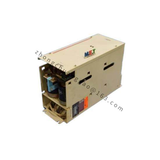
Technical Specifications
Input supply: 200 to 240 V AC, 3 phase.
Total rated power: 5.6 kW.
Total maximum output current: 32 A.
Axes: 6 independent servo outputs.
Compatible motors: Fanuc Alpha i series robotic servo motors.
Communication: FSSB high speed optical serial bus, COP10A interface.
Encoder support: Fanuc pulse and absolute encoders.
Cooling: internal axial fan.
Protection class: IP20.
Operating temperature: 0 to 55 °C.
Dimensions: approximately 350 x 350 x 150 mm.
Weight: approximately 10 kg.
Functional Features
Integrated rectifier and six inverter sections reduce cabinet wiring.
Three loop digital control covering position, speed, and current.
Vector control for synchronized multi axis robot motion.
Dynamic braking circuit for emergency stop and regenerative energy release.
Hardware protection for overcurrent, overvoltage, undervoltage, overtemperature, encoder fault, short circuit, and motor overload.
Status and alarm indicators for rapid fault identification.
Application Scenarios
Fanuc six axis industrial robot body servo drives.
Robotic handling, welding, palletizing, and assembly cells.
Machine tool multi axis auxiliary servo systems where six axis integrated drive is specified.
Packaging and material transfer automation with centralized servo power.
Performance Parameters
32 A total output capacity across six robotic joints.
5.6 kW aggregate rated power according to standard configuration.
FSSB optical communication for noise immune command transfer.
Full digital current regulation for accurate torque response.
Material And Construction
Sheet metal cabinet mounting chassis.
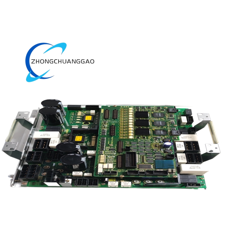
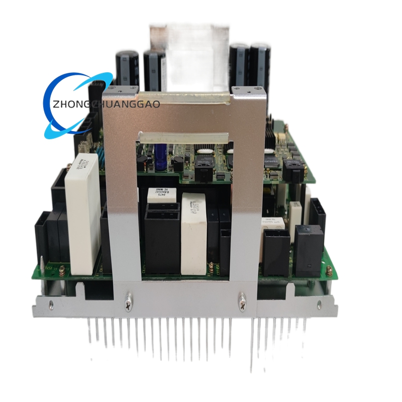
Internal power module, inverter modules, and control boards.
Axial cooling fan assembly.
Optical FSSB connectors and servo output terminals.
Diagnostic LED panel with alarm indication.
Working Principle
The module rectifies incoming three phase AC to the internal DC bus. The CNC or robot controller sends axis commands through the FSSB optical link. Each inverter section converts DC bus power into controlled three phase current for one joint motor. Encoder feedback closes the position, speed, and current loops. The braking circuit absorbs regenerative energy during deceleration and emergency stop.
Installation Requirements
Install inside a controlled electrical cabinet with forced ventilation.
Mount on the designated robot controller shelf or fixing frame.
Route FSSB fiber with approved bend radius and clean connector ends.
Connect three phase input with proper grounding and overcurrent protection.
Verify robot zero data and controller backup before module replacement.
Usage Precautions
Operate only in IP20 cabinet environments free from direct coolant and heavy dust.
Do not bend or contaminate FSSB optical connectors.
Backup robot mastering data and controller memory before service.
Check fan operation regularly and replace blocked or failed cooling fans.
Reset and analyze alarm codes before restarting after a fault.