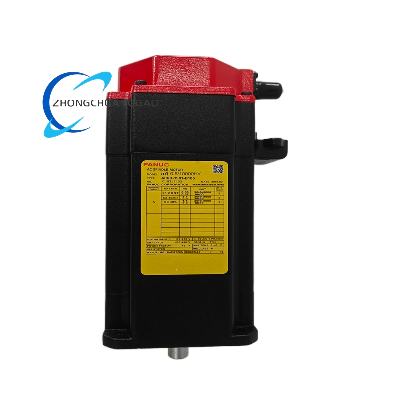
FANUC A06B-1501-B105
Product Introduction
This spindle product is used in machine tool main drive systems for milling, turning, grinding, and rigid tapping. Supplier documentation lists it both as an Alpha i AC spindle motor and, in some amplifier listings, as an Alpha i spindle amplifier configuration; verify the exact shipped unit type from the nameplate and order documents.
Detailed content
Technical Specifications
Motor configuration: Alpha i AC spindle motor family.
Drive interface: serial spindle communication with Fanuc CNC amplifier.
Amplifier mains where supplied as spindle drive: typically 200 to 240 V AC three phase; some Alpha i spindle amplifier listings state DC bus 283 to 339 V DC with 200 V AC three phase output.
Cooling: fan assisted motor cooling; amplifier internal fan where applicable.
Feedback: serial spindle encoder.
Thermal protection: integrated thermal sensor.
CNC communication: high speed serial link according to amplifier and control combination.
Operating temperature: 0 to 40 °C ambient for typical spindle installation.
Duty: continuous S1 in standard machine tool applications.
Amplifier specific reference from supplier listings:
DC bus input: 283 to 339 V DC.
Three phase output: 200 V AC class, high continuous current ratings according to amplifier model.
Control power: 24 V DC external supply where used as amplifier.
Communication: COP high speed serial fiber bus.
Compatible controllers: 0i B, 0i MF plus, 31i B, 32i B, 35i B according to amplifier listing.
Functional Features
Stable torque output across machining speed ranges.
Spindle orientation for tool change and indexing.
Rigid tapping through serial encoder feedback.
C axis control where amplifier and parameter configuration support it.
Smooth low speed cutting with reduced thermal drift.
Application Scenarios
Vertical machining centers.
Horizontal machining centers.
CNC lathes and turn mill machines.
Grinding machines requiring low vibration rotation.
Retrofit projects replacing legacy Fanuc spindle systems.
Performance Parameters
Continuous duty under fan assisted cooling.
Serial encoder based speed and position feedback.
High response acceleration according to amplifier capacity.
Orientation accuracy governed by encoder resolution and parameter setup.
Material And Construction
Laminated stator core with insulated windings.
Precision spindle bearings and shaft assembly.
Integrated fan housing for forced cooling.
Serial encoder or resolver interface module.
Flange and coupling interface for headstock installation.
Working Principle
The CNC sends spindle speed and orientation commands through the serial amplifier link. The drive converts DC bus or rectified AC power into controlled three phase output. The spindle motor rotates the machine tool main shaft. The encoder returns speed and position data for closed loop control, orientation, and rigid tapping.
Installation Requirements
Mount the motor flange to the spindle headstock with proper alignment.
Align the coupling to the machine spindle within specified runout limits.
Connect the serial encoder cable with shielded routing.
Install the matching Alpha i spindle amplifier with correct DC bus and control power.
Set spindle parameters, orientation offset, and thermal thresholds in the CNC.
Usage Precautions
Confirm motor, amplifier, and CNC model compatibility before commissioning.
Check encoder and thermal sensor continuity before energizing.
Maintain cooling fan operation and cabinet ventilation.
Do not exceed rated bus voltage, output current, and ambient temperature.
Backup spindle parameters before hardware replacement.