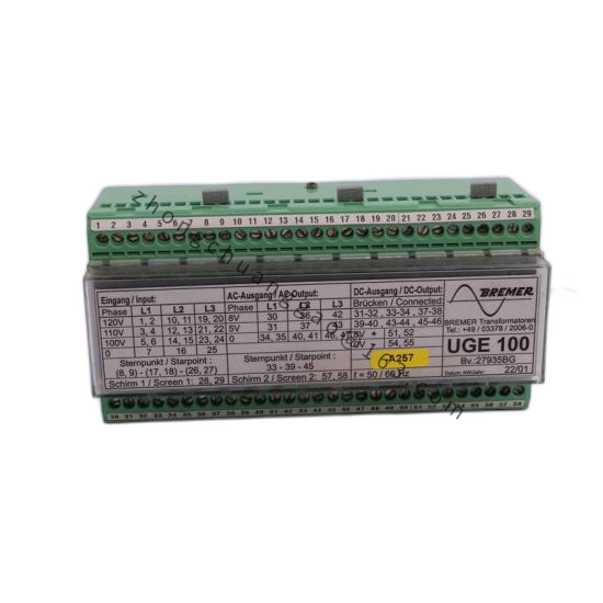
Technical Specifications
- Measurement range: 0.001 Hz to 99.9 kHz programmable
- Analog output: 0–20 mA, 4–20 mA, 0–10 VDC, 2–10 VDC
- Accuracy/linearity: ±0.05%
- Input sensitivity: 50 mV to 80 Veff AC-coupled; 3 V to 80 Veff up to 99.9 kHz depending on range
- Sensor supply: 15 VDC or 8 VDC, maximum 60 mA
- Power supply: 115 VAC or 230 VAC ±10%; optional 18–30 VDC galvanically isolated
- Measurement principle: multi-period/interval frequency evaluation
- Calculation cycle: approximately 3 ms
- Temperature drift: 30 ppm/°C
- Housing/protection: plastic DIN-rail housing, IP50
- Status: listed as discontinued by OEM from 31 December 2021
Functional Features
Microprocessor-based frequency scaling, coding-switch range selection, internal low-pass filtering, sensor excitation output, DIN-rail installation, analog output linearization.
Application Scenarios
Turbine flowmeter pulse conversion, extruder line-speed feedback, centrifugal/agitator rpm transmission, magnetic pickup tachometer conditioning, legacy pulse-to-analog retrofit.
Material Composition
Flame-retardant plastic DIN housing, PCB, coding switches, terminal block, isolated power section.
Structural Characteristics
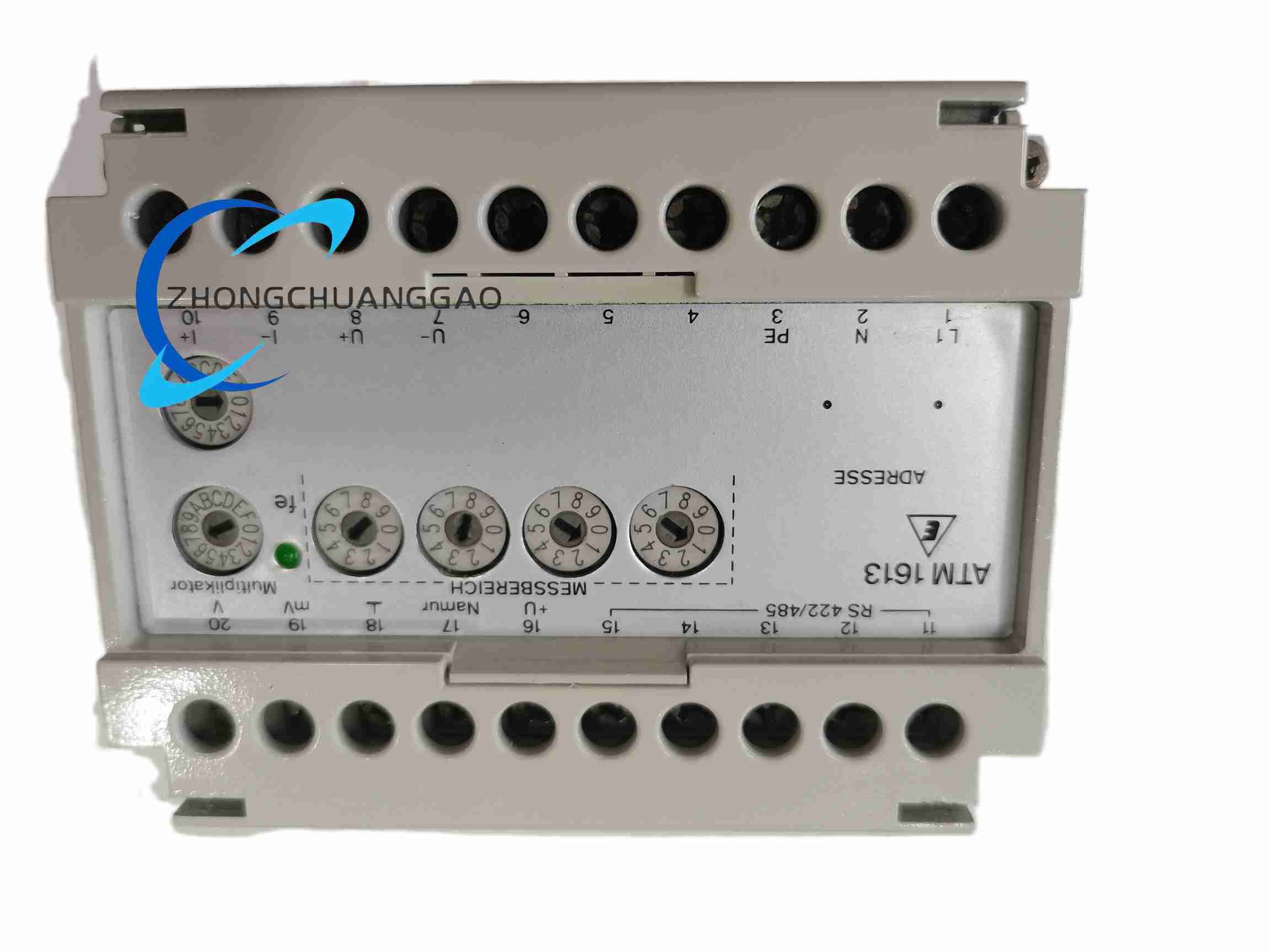
Compact DIN-rail module, front coding switches, AC/DC power terminals, frequency input terminals, analog output terminals, sensor supply terminals.
Working Principle
The input stage couples AC/sqare pulses, measures interval or period over multiple cycles, computes frequency and converts the result through calibrated DAC/scaling into 0–20 mA, 4–20 mA, 0–10 V or 2–10 V analog output.
Installation Requirements
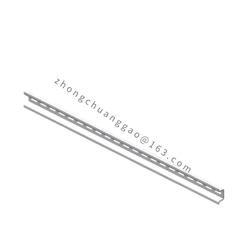
Mount on 35 mm DIN rail in cabinet. Select 115/230 VAC or DC power variant by internal jumper/wiring. Set measurement range with coding switches before energizing. Use shielded sensor cable, grounded at one point. Connect analog output to isolated PLC analog input.
Usage Precautions
Verify coding-switch range against maximum input frequency to prevent saturation. Confirm AC power jumper before energizing. Keep low-level sensor cables away from VFD/motor power. For obsolete units, bench-test output linearity before field reuse.